8-14
–+
ELEC
E
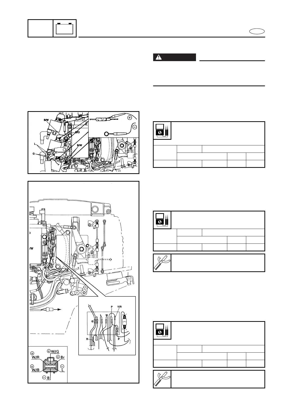
IGNITION SYSTEM
IGNITION SYSTEM PEAK VOLTAGE
WARNING
When checking the CDI unit do not touch
any of the connections of the digital tester
lead wires.
1. Measure:
● CDI unit output peak voltage
Above specification → Replace the
ignition coil.
Lead color:
#1: B/O – B, #2: B/W – B,
#3: B/Y – B
r/min
Circuit Loaded
Cranking 1500 3500
V 4.5 190 185 105
2. Measure:
● Charge coil output peak voltage
Below specification → Replace the
charge coil.
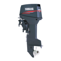
3. Measure:
● Pulser coil output peak voltage
Below specification → Replace the
pulser coil.
Above specification → Replace the
CDI unit.
Lead color:
Br – L
r/min
Circuit Loaded
Cranking 1500 3500
V 175 210 205 115
Test harness:
YB-38832/90890-06772
Lead color:
#1: W/R – B, #2: W/B – B,
#3: W/G – B
r/min
Circuit Loaded
Cranking 1500 3500
V 4.0 4.0 11.0 20
Test harness:
YB-38832/90890-06772