8-30
–+
ELEC
E
POWER TRIM AND TILT (PTT) CONTROL SYSTEM
FUSE
Refer to “STARTING SYSTEM”.
BATTERY
Refer to “GENERAL” in chapter 3.
PTT MOTOR
Refer to “PTT MOTOR DISASSEM-
BLY” in chapter 7.
PTT RELAY
1. Check:
● PTT relay continuity
Out of specification → Replace.
PTT relay continuity:
Sky blue 1 – Black 2
Light green 3 – Black 2
Blue 4 – Black 2
Green 5 – Black 2
Continuity
Blue 4 – Red 6
Green 5 – Red 6
No continuity
6
4
1
5
3
2
B R
L
Sb
G
Lg
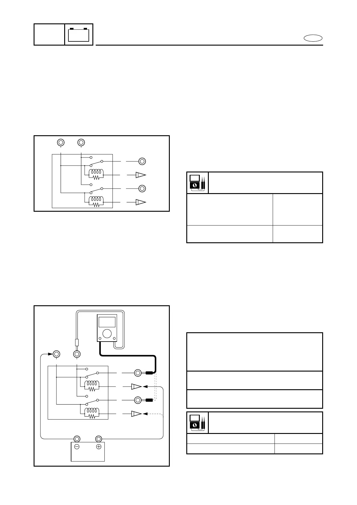
2. Check:
● PTT relay operation
Out of specification → Replace.
Checking steps:
● Connect the tester between the PTT
relay terminals.
● Connect a 12 V battery.
Å Sky blue 1 lead → Positive terminal
Black 2 lead → Negative terminal
ı Light green 3 lead → Positive terminal
Black 2 lead → Negative terminal
PTT relay continuity:
Å Red 4 – Blue 5 Continuity
ı Red 4 – Green 6 Continuity
4
5
1
6
3
2
B R
L
Sb
G
Lg
+–
Å
Å
ı
ı