1-1
IM WT18
O
1E-02EN
1.1 Configuring the Wiring System Settings
This section explains the following settings for wiring systems:
• Wiring system
• Wiring unit
• Wiring pattern
► “Wiring System (Wiring)” in the features guide
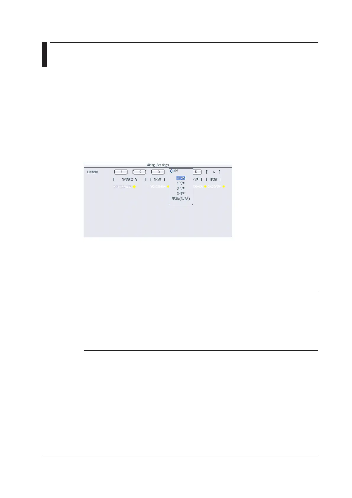
Wiring Settings (Wiring Settings)
Press WIRING and then the Wiring soft key to display the following screen.
Set the wiring system (1P2W, 1P3W, 3P3W, 3P4W, 3P3W(3V3A)).
When you select an input element, the wiring systems that you can select are displayed. Select the wiring
system from those displayed.
Wiring System Pattern
• If you select 1P3W, 3P3W, 3P4W, or 3P3W(3V3A) for the wiring system, the wiring unit is set with the two
or three input elements adjacent to the selected element whose element numbers are larger than the
selected element.
• On models that have six input elements installed, up to three wiring units (ΣA, ΣB, and ΣC) are
automatically set. The wiring unit symbols ΣA, ΣB, and ΣC are attached to the element numbers in order,
starting with the smallest number.
Note
• Because the wiring system with the largest element number is automatically determined according to the
settings of the wiring systems with smaller element numbers, the element with the largest element number
cannot be selected.
• You cannot set the wiring units for larger element numbers before the wiring units for smaller element
numbers.
• Tomeasurevoltage,current,andactivepowerΣfunctionsusinghighspeeddatacapturing,setthewiring
system to 3P4W or 3P3W (3V3A). When the wiring system is set to 1P3W or 3P3W, voltage, current, and
activepowerΣfunctionsarenotmeasured.
Chapter 1 Basic Measurement Conditions

 Loading...


