2-1
IM WT18
O
1E-02EN
2.1 Setting Harmonic Measurement Conditions
This section explains the following settings for harmonic measurement conditions. This feature is
available on models with the /G5 or /G6 option.
• Input element group
• PLL source
• Measured harmonic order
• Distortion factor equation
► “Harmonic Measurement Conditions (Option)” in the features guide
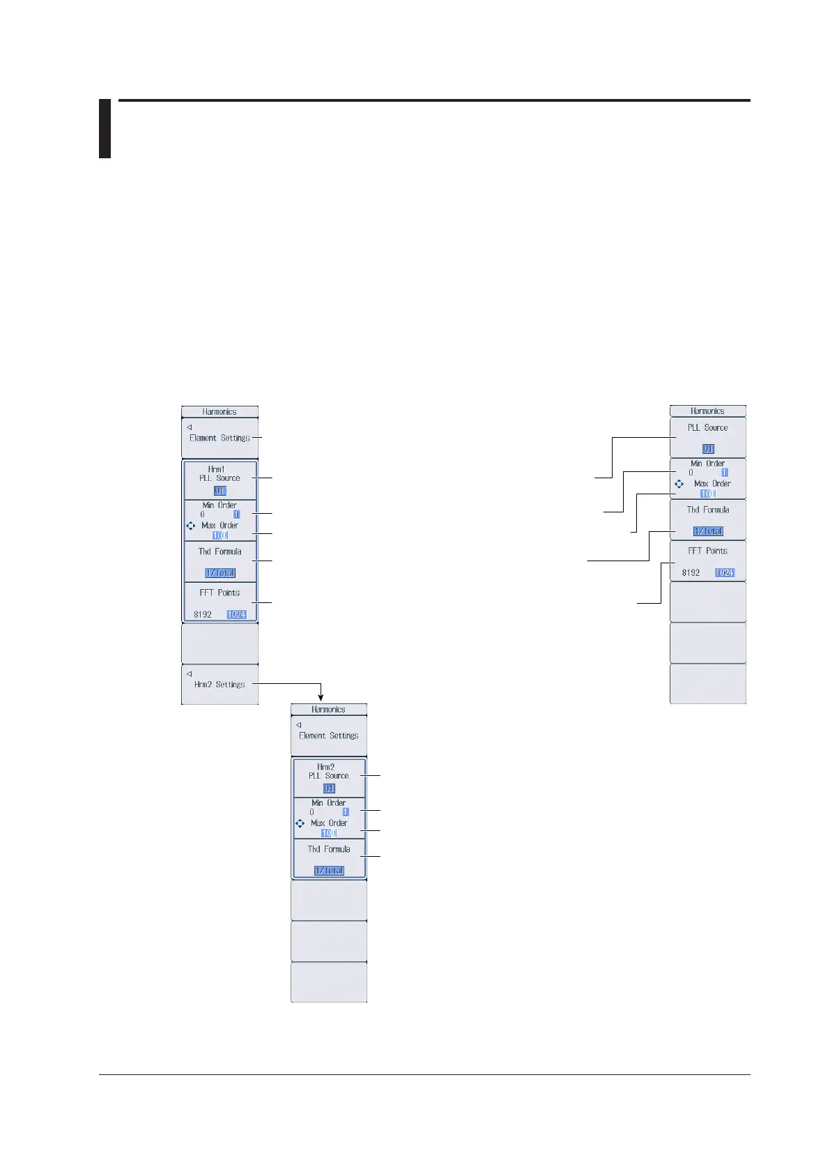
Harmonics Menu
Press HRM SET to display the following menu.
Configure the input element groups.
1
Set the PLL source (U1, I1, U2, I2, U3, I3, U4, I4, U5, I5, U6, I6,
Ext Clk).
Group Hrm1
Set the minimum value of the measured harmonic order (0, 1).
Set the maximum value of the measured harmonic order (1 to 500).
Set the distortion factor equation (1/Total, 1/Fundamental).
Set the PLL source (U1, I1, U2, I2, U3, I3, U4, I4, U5, I5, U6, I6,
Ext Clk).
Group Hrm2
Set the minimum value of the measured harmonic order (0, 1).
Set the maximum value of the measured harmonic order (1 to 500).
Set the distortion factor equation (1/Total, 1/Fundamental).
Menu on a Model with the /G6 Option
(Dual harmonic measurement)
Menu on a
Model with the
/G5 Option
Set the number of FFT points when the data update interval is Auto.
(1024, 8192).
2
Configure the Group Hrm2.
1
1 You can set this when the data update interval is not Auto.
2 You can set this when the data update interval is Auto.
Chapter 2 Harmonic Measurement Conditions (Option)

 Loading...


