13185L-002 Rev. A 1/24/06 110XiIIIPlus Maintenance Manual Page 4-61
Maintenance Section 4
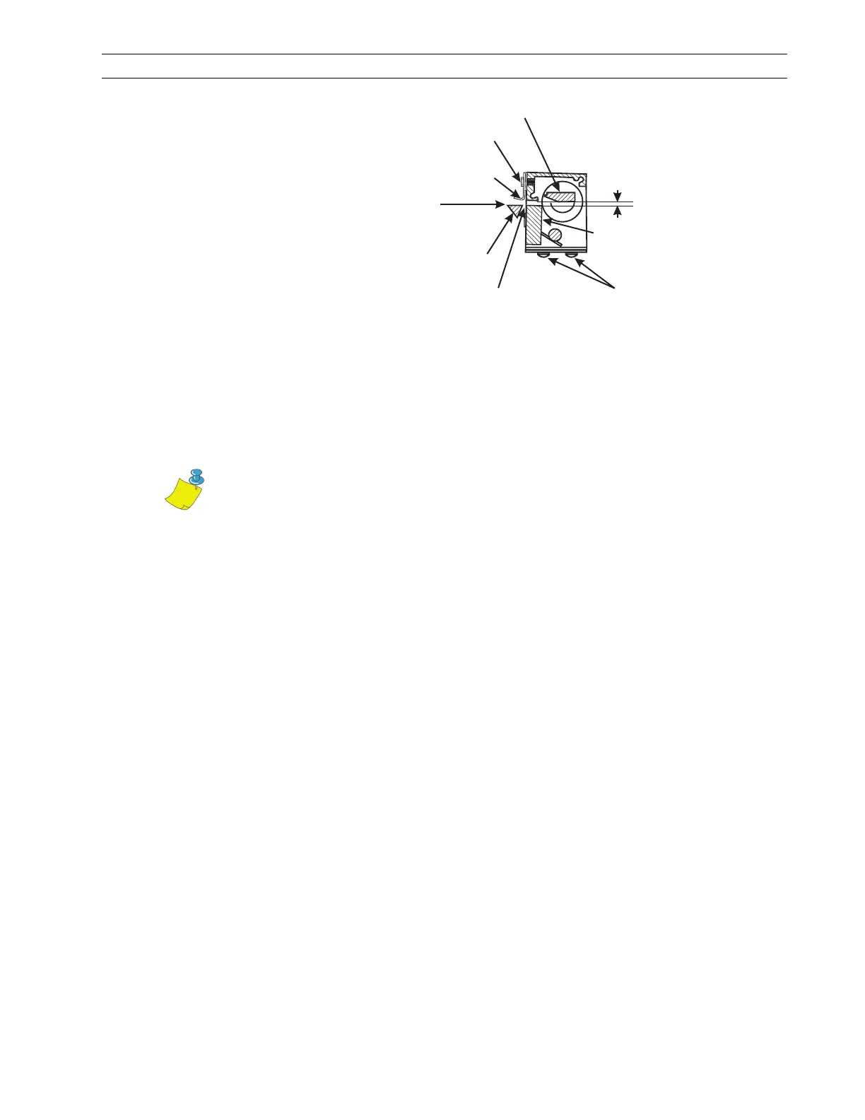
Figure 4-36. Mechanical Assembly Position
5. Position the upper drive arm out from the cutter frame so its flat surface is flush with
the end of the rotary cutter blade shaft.
6. Use an Allen wrench socket on a torque wrench and tighten the screw until the slot
closes or until a torque of 100 inch-pounds (11.3 N
•m) is achieved.
7. With a pen, draw a line across the outer face of the upper drive arm and the end of
the cutter blade shaft. If cutter operation problems occur, this mark shows whether
the alignment of the clamp and the cutter blade shaft has changed.
8. Refer to RRP No. 2 on page 4-16. Replace the electronics cover.
9. Reconnect the AC power cord and turn the printer On (l). Enter Configuration Mode
and set the printer to Cutter Mode. Save as PERMANENT and turn the printer Off
(O).
10. Load media and ribbon, press and hold PAUSE while turning the printer On (l), and
run labels through the printer. Test the cutter for proper operation.
11. Test the printer timing by feeding maximum-width label stock through the printer
and ensuring a complete cut occurs. If necessary, repeat the retiming procedure.
Rotary Cutter Blade
Upper Cutter Bracket
Mounting Screw
Media Guide
0.100 in.
(2.5 mm)
Ensure the top of the tear-off
bar is positioned above or
level with the top of the
rear cutter blade.
Tear-Off
Bar
Clearance of 0.030 in. (0.7 mm)
minimum between rear cutter blade
and tear-off bar
Screws control position
of cutter module and
squareness to media.
Rear Cutter
Blade
Relative position of the rotary cutter blade when the drive link assembly
is stopped by the optical sensor, when the power is On()inCutter Mode.l
Note • Overtightening the screw can damage the drive arm and strip the
threads.
 Loading...