Page 4-106 110XiIIIPlus Maintenance Manual 13185L-002 Rev. A 1/24/06
Section 4 Maintenance
Coax Communications Interface Boards
Install
1. Refer to RRP No. 1 on page 4-14. Turn the power Off (O) and disconnect the AC
power cord. Disconnect the data cable.
2. Refer to RRP No. 2 on page 4-16 and remove the electronics cover.
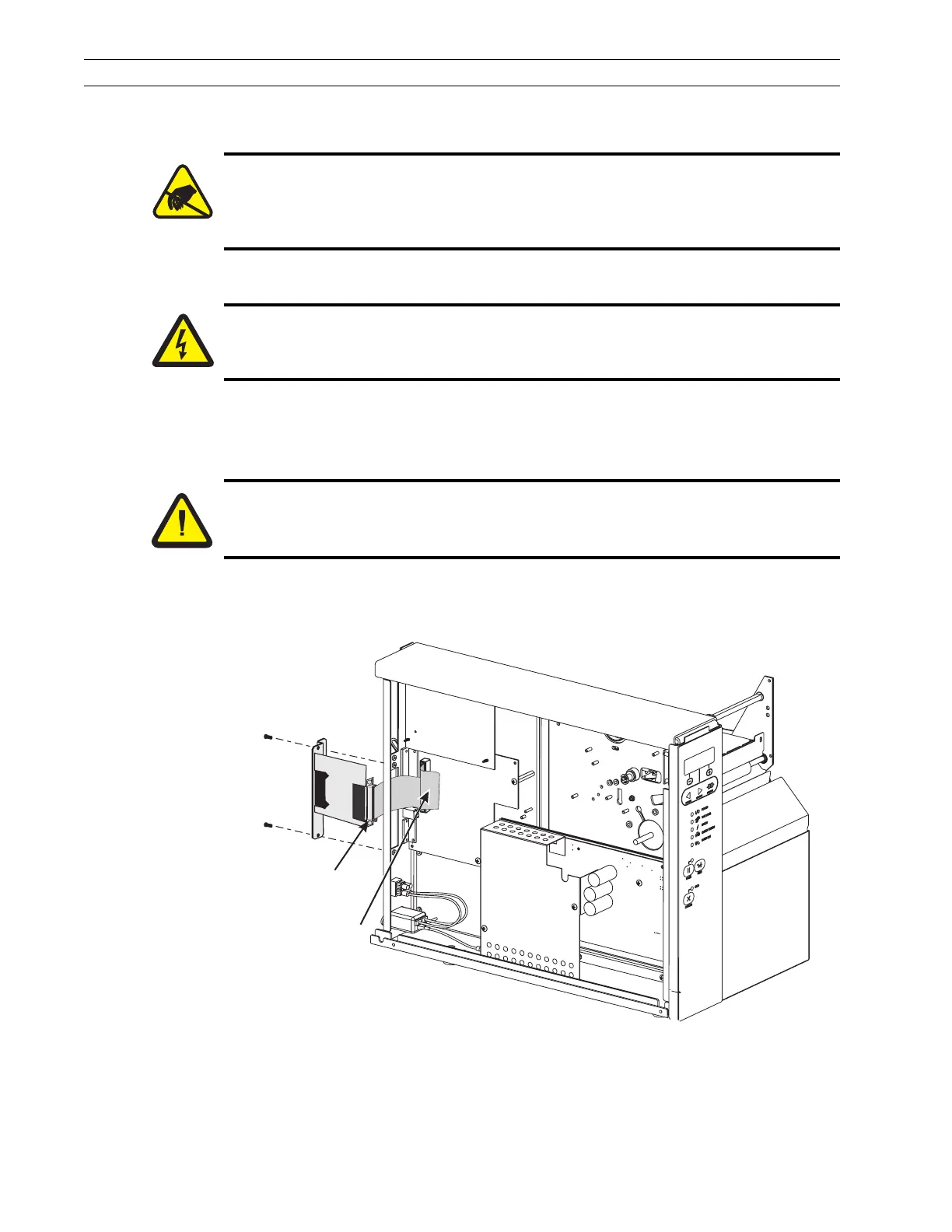
3. Refer to Figure 4-70. At the rear of the printer, remove and retain the two screws
and the blank cover plate or existing interface board positioned next to the main
RS-232 and parallel interface connectors.
Figure 4-72. Coax Communications Interface Board Installation
4. Plug the 40-pin interface data cable into the keyed interface data cable connector
P21on the main logic board.
Caution:
The printer electronics are susceptible to static discharge. Before proceeding, it
is highly recommended the technician wear an antistatic wrist strap connected
to the printer chassis.
Caution:
Unless indicated otherwise, turn the printer Off (O) and disconnect the printer
from the power source before performing the following maintenance.
Caution:
This installation must be performed by a qualified service technician.
Data Cable
Connector
Ribbon Cable
 Loading...