13185L-002 Rev. A 1/24/06 110XiIIIPlus Maintenance Manual Page 4-133
Maintenance Section 4
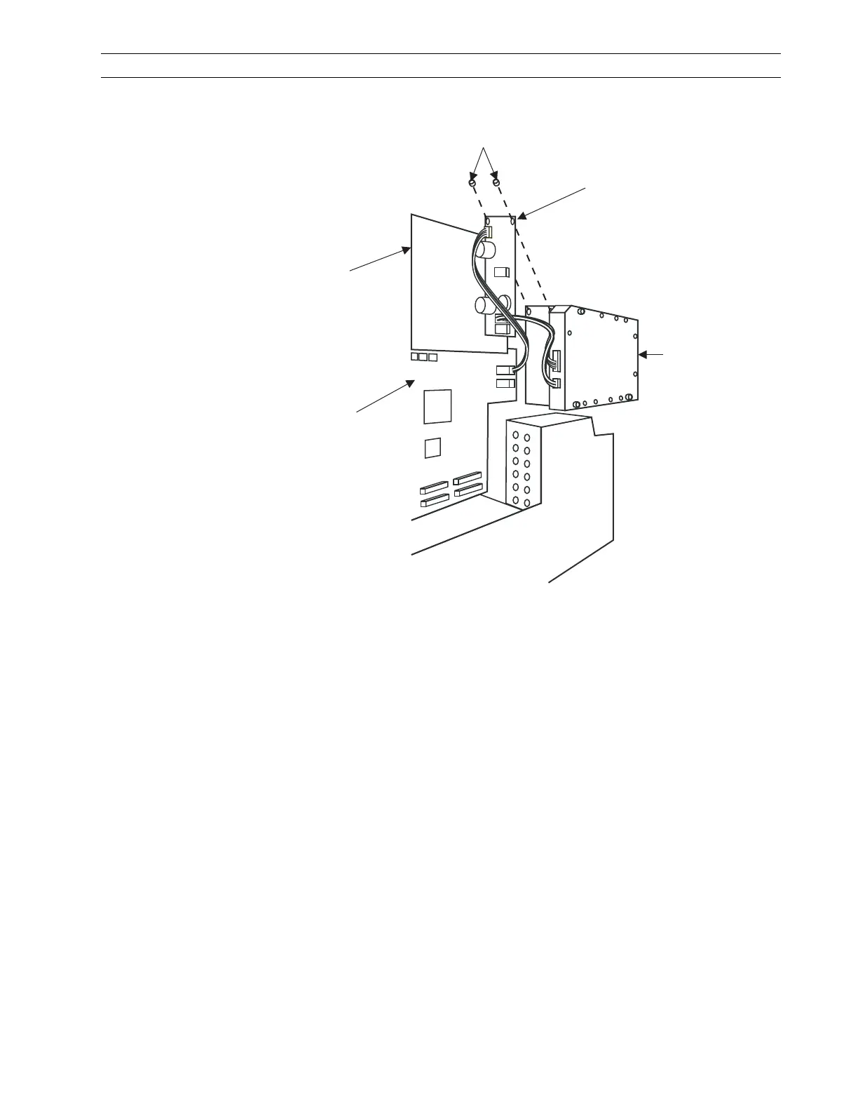
3. Refer to Figure 4-92. Disconnect all connectors from the power PC board assembly.
Figure 4-92. Remove and Install the Power PC Board Assembly
4. Loosen and remove the power PC board assembly mounting hardware. Retain the
mounting hardware.
5. Remove the power PC board assembly from the printer.
Install Power PC Board Assembly
1. Refer to Figure 4-92. Mount the new power PC board assembly onto the printer
using the previously removed mounting hardware.
2. Connect the harness from the main logic board and the harness from the reader PC
board assembly to the new power PC board assembly.
3. Refer to RRP No. 2 on page 4-16 and reinstall the electronics cover.
4. Reconnect the data cables and AC power cord.
5. Turn the printer On (l).
RFID Power PC Board
Mounting Screws
Main Logic
Board
PCMCIA
Option Board
RFID Power
PC Board
RFID Reader
Board
 Loading...