Page 4-114 110XiIIIPlus Maintenance Manual 13185L-002 Rev. A 1/24/06
Section 4 Maintenance
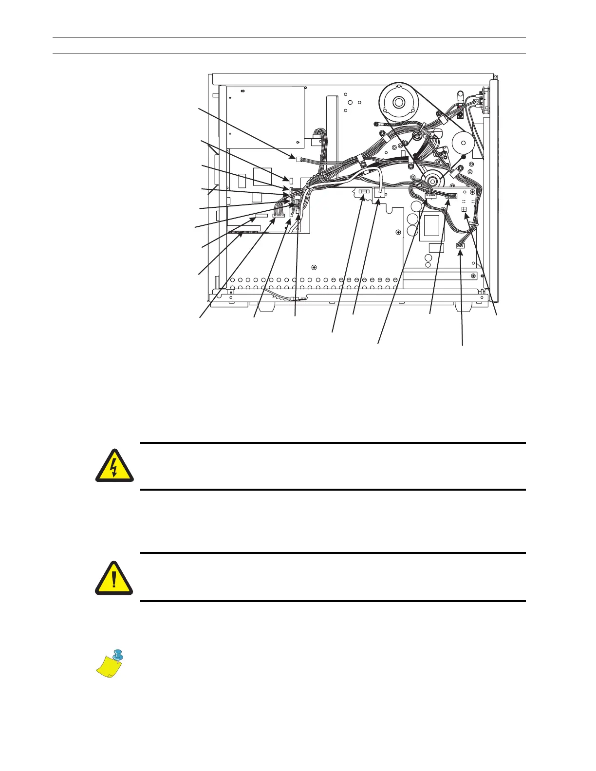
Figure 4-75. PCB Location and Interconnections
Disassemble the Printer
The printer must be partially disassembled to install the parts in this kit.
1. Refer to RRP No. 1 on page 4-14. Turn the printer Off (O) and remove the power
cord. Disconnect the printer communications cable.
2. Refer to RRP No. 2 on page 4-16 and remove the electronics cover.
3. Refer to RRP No. 3 on page 4-17. Note and remove all connectors from the AC/DC
power supply assembly.
Cutter
Option
Front Panel
Interface
LCD
Display
Lower
Media Sensor
Ribbon
Sensor
Head-Open
Sensor
Printhead
Data
Black-Mark
Sensor
Lower
Take-Label
Sensor
Upper
Take-Label
Sensor
Upper
Media Sensor
Stepper
Motor
Main Logic
PCB
PCMCIA
Option Board
AC/DC
Power
PCB
Printhead
Power
AC
Input
AC
Power
Fuse
Main Logic
Board
Power
Cutter
Option
P6
P25
P27
P8
P2
P1
P3
P32
P31
P19
P5
P10
Caution:
Unless indicated otherwise, turn the printer Off (O) and disconnect the printer
from the power source before performing the following maintenance.
Caution:
This installation must be performed by a qualified service technician.
Note • For part identification, see Table 4-6.
 Loading...