Page 4-66 110XiIIIPlus Maintenance Manual 13185L-002 Rev. A 1/24/06
Section 4 Maintenance
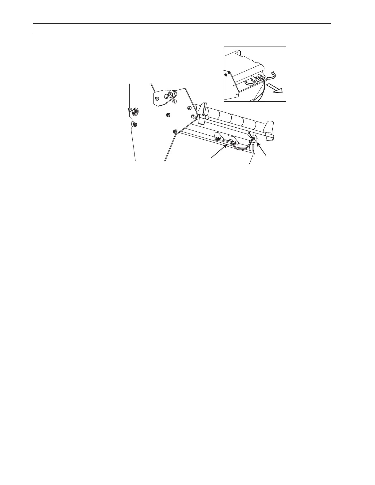
Figure 4-40. Lower Media Sensor and Bracket
7. Refer to Figure 4-39. Locate the electrical leads from the two sensors. Open the
cable clamps and follow the sensor leads to the main logic board connectors.
8. Remove these connectors.
9. From the media side of the printer, remove the grommet from the slot in the printer
main frame. Gently pull the sensors while guiding the wires through the hole in the
main frame.
10. Remove the upper and lower sensors.
Install the Sensor
1. Refer to Figure 4-38. Guide the wires of the new upper and lower media sensors
through the main frame and install the split grommet into the main frame.
2. Connect the leads of the sensors to the main logic board, P-8 and P-10.
3. Reinstall the upper sensor bracket and secure it with thumbscrews.
4. Refer to Figure 4-39. Reinstall the pivot pin and dancer spring.
5. Refer to Figure 4-40. Slightly spread the lower media bracket open and install the
lower media sensor.
6. On the electronics side of the printer, route the electrical leads through the cable
clamps and reinstall a new cable tie.
7. Resecure cable clamps with the nuts.
8. Reinstall the electronics cover.
9. Refer to Position Media Sensors on page 2-18 and adjust the position of the sensors.
10. Reinstall the media and ribbon and close the media cover.
11. Reconnect the data cables and the AC power cord.
12. Turn the printer On (l).
Lower
Media Sensor
Grommet
 Loading...