Page 4-130 110XiIIIPlus Maintenance Manual 13185L-002 Rev. A 1/24/06
Section 4 Maintenance
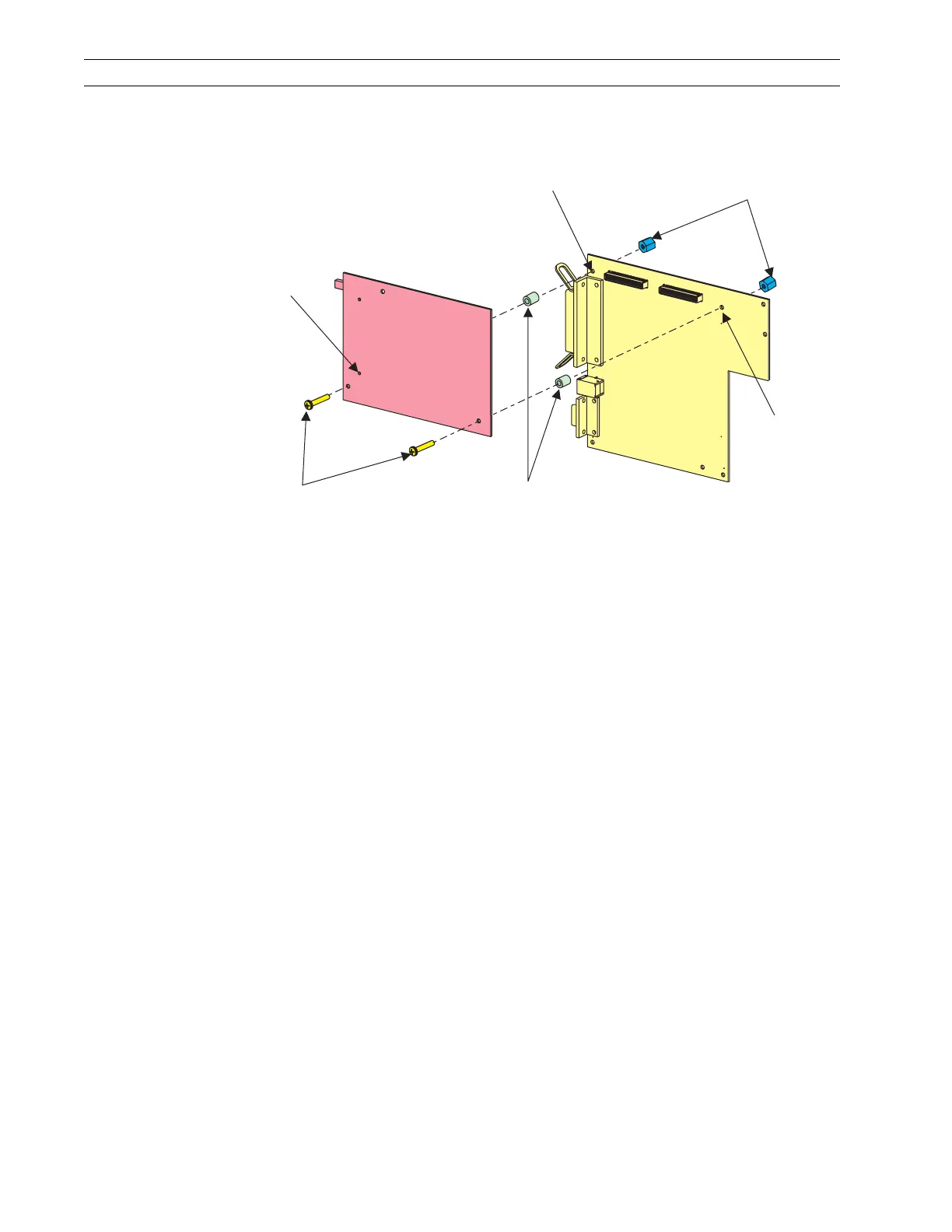
2. Slide one of the new spacers between the PCMCIA Option board and the MLB at
either one of the mounting holes.
Figure 4-90. Install Spacers
3. Insert one of the screws through the mounting hole in the wireless PCMCIA board,
spacer, and MLB.
4. Secure the screw with one of the plastic nuts.
5. Repeat steps 2, 3, and 4 for the other mounting hole.
6. Ensure that the PCMCIA option board is seated into the MLB connectors.
7. Install the PCMCIA Option board using the hardware previously removed.
8. Refer to Figure 4-9 on page 4-19. Reinstall the option card, if installed, back into the
card slot in back of the printer.
9. Refer to RRP No. 2 on page 4-16 and reinstall the electronics cover.
10. Ensure the printer is turned Off (O) and reconnect the AC power cord.
11. Turn the printer On (l).
Plastic Nuts
P24
P23
Mounting
Hole
Mounting
Hole
Mounting
Hole
Plastic
Spacers
Screws
 Loading...