ZEISS OPERATION Axio Imager 2
Illumination and contrast methods
182 430000-7544-001 01/2016
• Push the Bertrand lens slider into the light path. Focus the axial figure by means of the lever of the
slider,
or,
on the tube lens turret, swivel the position with the Bertrand lens into the light path, and focus the
axial figure by turning the focusing wheel.
(5) Evaluation
Crystalline anisotropic specimens can be classified into optically uniaxial and biaxial specimens, each with
an "optically positive" or "optically negative" character.
Uniaxial crystals exhibit a black cross if the optical axis is oriented parallel to the viewing direction.
Dependent on the degree of birefringence and the specimen thickness, concentrically arranged
colored interference fringes (the so-called isochromats) might appear (see Fig. 204, second row).
This cross remains closed when you rotate the stage. It can be located inside or outside the imaged
objective pupil, depending on the position of the section.
With optically biaxial crystals, the cross resolves into two dark hyperbola branches (the so-called
isogyres) depending on stage rotation which are surrounded by colored interference patterns
depending on the amount of birefringence and specimen thickness (suggestive of the figure "8").
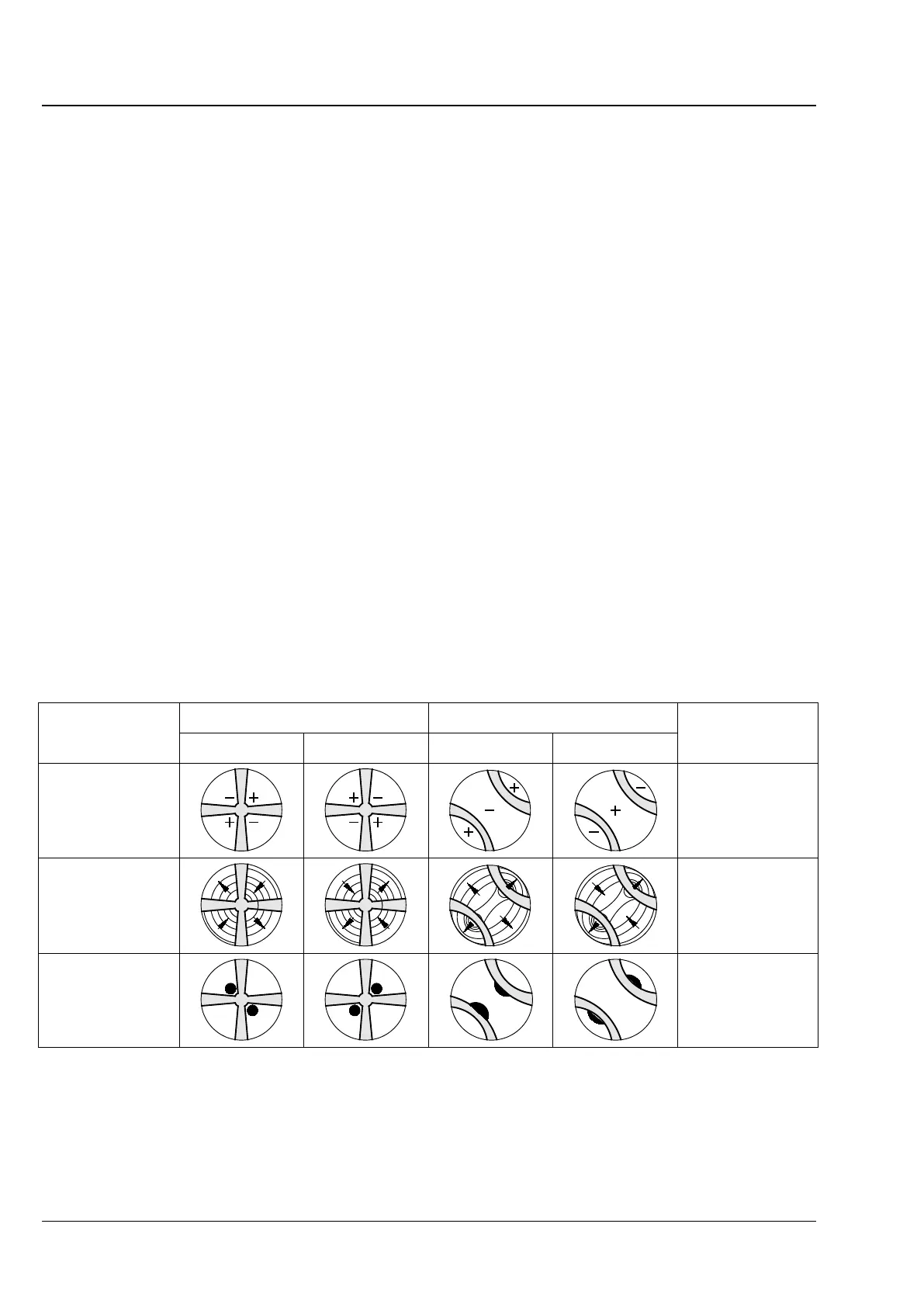
Inserting a compensator λ (473704-0000-000) or λ/4 (473714-0000-000) or a wedge compensator 0-4 λ
(000000-1140-663) in the compensator slot when the initial state of the axial figure is as shown in
Fig. 204 results in the following changes in color shown schematically (blue and yellow areas) to the axial
figure, thus allowing differentiation into "optically positive" and "optically negative".
Optically uniaxial Optically biaxial
Positive Negative Positive Negative
λ plate
(white→ blue
→ yellow)
+ = blue
– = yellow
Quartz wedge
(Direction of motion
during insertion)
Direction of
movement
λ/4 plate
(position of black
spots)
Fig. 204 Determining the optical character