ZEISS OPERATION Axio Imager 2
Axio Imager 2 operation and function controls (motorized version)
92 430000-7544-001 01/2016
Binocular phototube with motorized eyepiece shutter (Fig. 80/1)
− In addition to the manually operated beam splitter, the binocular phototube with motorized eyepiece
shutter 30°/25 (425506-0000-000) is equipped with a motorized eyepiece shutter which is operated
via the button on the right side (alternately on / off) or via the TFT display.
Motorized camera path deflection, left (Fig. 80/2)
− The motorized camera path deflection (100:0/50:50) is exclusively operated via the TFT display.
Switch off the microscope before inserting stop slider mot., double filter wheel mot. and FL
attenuator discrete mot. into the corresponding slots.
Slot F for stop slider mot. (Fig. 80/3) with centerable luminous-field diaphragm
− The motorized stop slider is to be inserted in the same way as the motorized double filter wheel
discrete mot. and the FL attenuator discrete mot.
− The diaphragm is opened or closed by pushing the respective button on the slider.
Slot for double filter wheel, discrete mot. for
reflected light (Fig. 80/4) and transmitted light
(Fig. 80/7)
− When using the HAL 100 halogen illuminator in
the reflected-light and the transmitted-light
path, the double filter wheel discrete mot. can
be used for brightness adjustment. This
contains four filter positions (neutral-filters) on
two filter wheels.
Gray filters are not suitable for
fluorescence applications, as they may
be damaged.
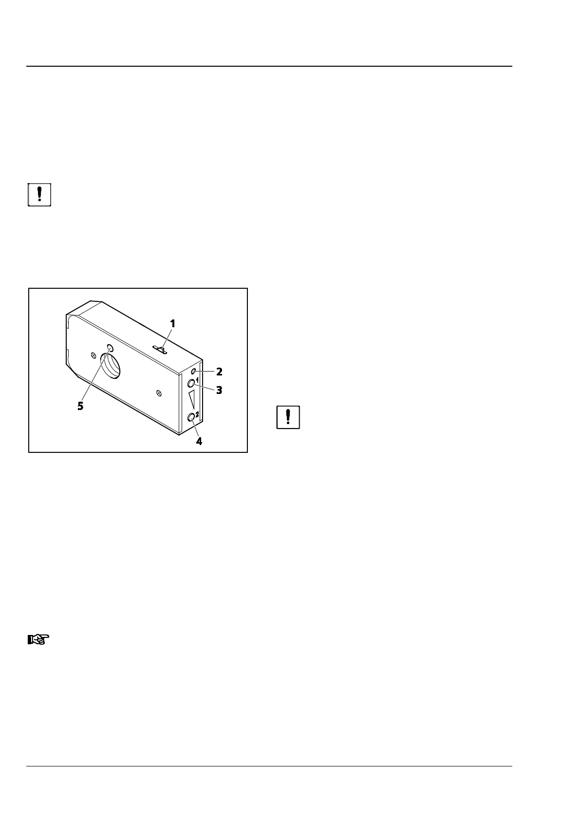
− Before inserting the filter wheel module, first
activate the click-stop mechanism (Fig. 81/1) by
pushing it in. At the right-hand front end
(Fig. 81/2) a small silver plate becomes visible.
Then push the filter wheel module into the corresponding slot until you hear it click into place.
− To remove the filter wheel module, introduce a screwdriver into the top hole (Fig. 81/2) and push in
the silver plate to deactivate the click-stop mechanism. Slightly cant the screwdriver in the hole and
pull the filter wheel module out of the slot.
− Adjust the desired positions of the filter wheels by pushing the top (Fig. 81/3) or the bottom button
(Fig. 81/4). When the filter wheel module has been removed, the selected transmission can be read
from the sight glass (Fig. 81/5). The positions of the two integrated filter wheels can be combined with
each another in any configuration.
The stop slider aperture / attenuator mot. are configured in the TFT (Fig. 160 on page 141.
Fig. 81 Inserting/removing double filter
wheel discrete mot.