9 of 14
Jun 2001
Electrical
Agilent 6890 Gas Chromatograph Service Manual
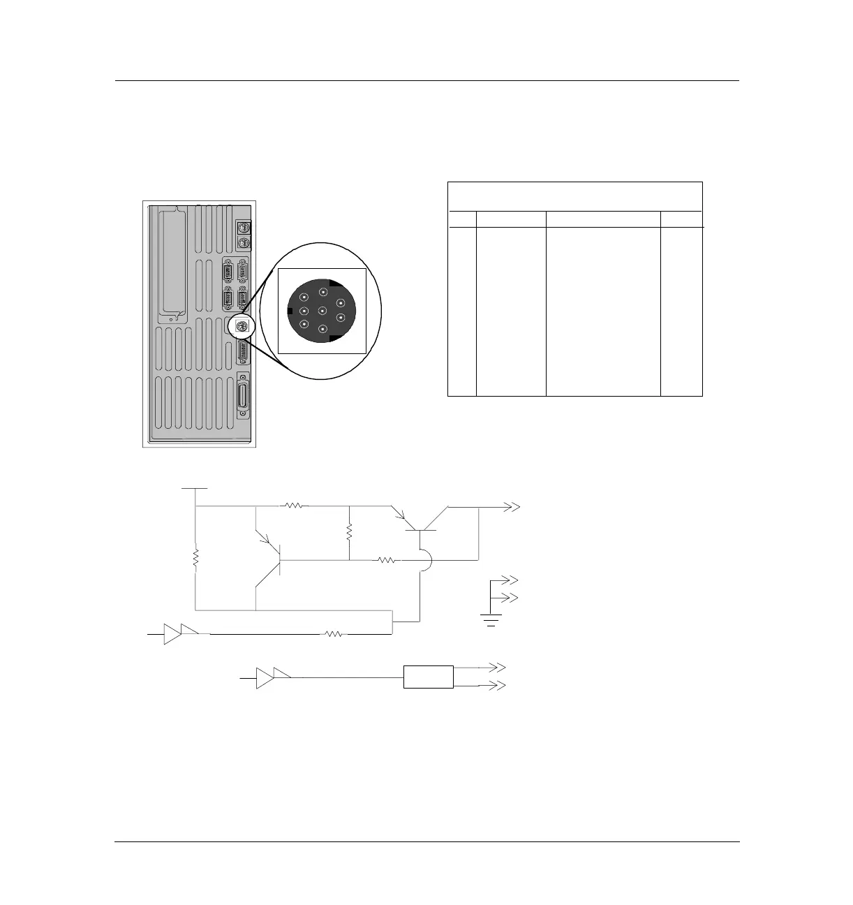
External Connectors, 6890A and 6890 Plus 1210
External event
External event
J4
External event
Pin Function Max. rating Valve
1 24 V Out 1 75 mA output 5
2 24 V Out 2 75 mA output 6
3 GND
4 GND
5 Contact 1 48V ac/dc, 250 mA 7
6 Contact 1 7
7 Contact 2 48V ac/dc, 250 mA 8
8 Contact 2 8
9 Chassis
GND
3
1
2
5
6
7
8
Note: The 24V OUT1 and 24V OUT2 signals are shown on the same
circuitry diagram below, however they each have their own distinct cir-
cuits. The CONTACT1 and CONTACT2 signals are presented in the
same manner. Bold designators refer to the bold signal to the right.
+ 24V
Current limited
R88
R87
11
U113
037
035
R207
R201
287
R208
R208
036
038
10
1 V24_OUT1
2 V24_OUT2
3 GND
4 GND
5 CONTACT_IN1
7 CONTACT_IN2
6 CONTACT_OUT1
8 CONTACT_OUT2
U5.5
U5.6
K2
Relay
K3
9 (Chassis)

 Loading...


