1 of 10
Jun 2001
Electrical
Agilent 6890 Gas Chromatograph Service Manual
1215 External Connectors, 6890N
Overview
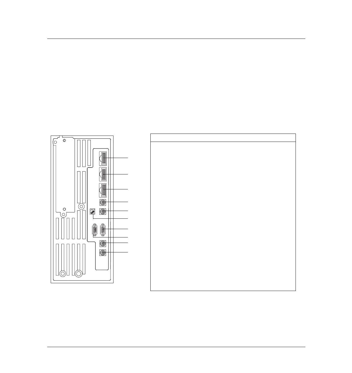
This section show the pinouts for the external connectors on the back of the
Agilent 6890N instrument. See section External Connectors, 6890A and 6890
Plus for the 6890A and 6890 Plus instruments.
These connectors are used for communications with external instruments.
Figure 1215-1 6890N GC external connections
Back of 6890N GC
S
A
M
P
L
E
R
1
S
A
M
P
L
E
R
2
T
R
A
Y
S
I
G
1
S
I
G
2
E
V
E
N
T
B
C
D
R
S
/
2
3
2
R
E
M
O
T
E
LAN
1
2
3
4
5
6
7
8
9
10
Number Description Connector
1 Sampler 1 – Communications and
power for the front injection tower
P4
2 Sampler 2 – Communications and
power for the back injection tower
P5
3 Tray – Communications and power for
the sample tray
P6
4 Signal 1 – Analog output for
integrators or A/D converters
J1
5 Signal 2 – Analog output for
integrators or A/D converters
J2
6 LAN – Local Area Network
7 RS-232 – For modem or non-Agilent
controller
JP1
8 Remote – Start/stop signals for use
with integrators, Mass Sensitive detec-
tors, and other sampling devices (e.g.
headspace)
JP1
9 Event – Contact closures and 24V out-
puts for valve control
J4
10 BCD input for stream selection valve J5

 Loading...


