1220 Main Board, 6890A and 6890 Plus
Connector electronics
2 of 10
Jun 2001
Electrical
Agilent 6890 Gas Chromatograph Service Manual
Connector electronics
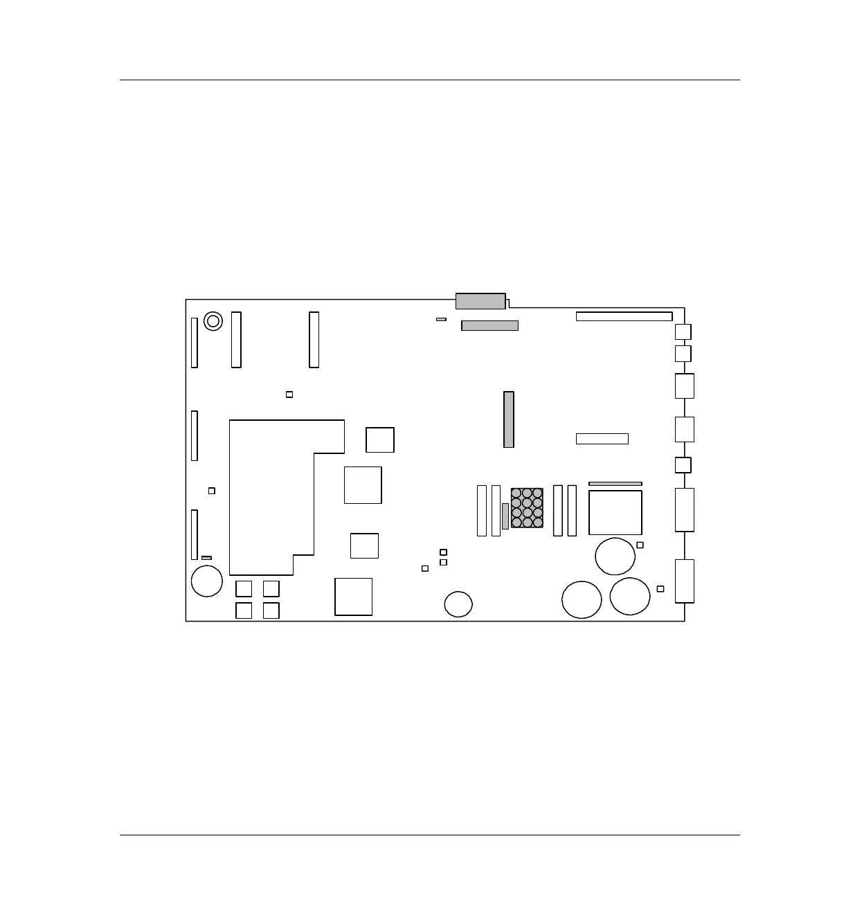
The table on the following page shows the pinouts for some of the internal
connectors on the main circuit board that can be probed for diagnostic
purposes. These connectors are shaded on the diagram below. These
connectors are used for communications within the instrument. All connector
pinout drawings are viewed from the component side of the board.
Figure 1220-2 Main board connectors
Hole for
Xfmr
Oven Access
Cutout
Beeper
P11 P1 P2
P12
P13
P17
GND
P15
DSP
CPU
GND
4 ROM
Sockets
3V
Lithium
battery
Gate
Array
P16
P21
P22
P3
J1
J2
JP2
J4
J6
J5
F2 F1
F4
F3
P18
+24V
–24V
+15V
–15V
+5v
Capacitor
Capacitors
cable
J8
J7
P19
Gate
Array
JP1

 Loading...


