Agilent 7820 GC Service
245
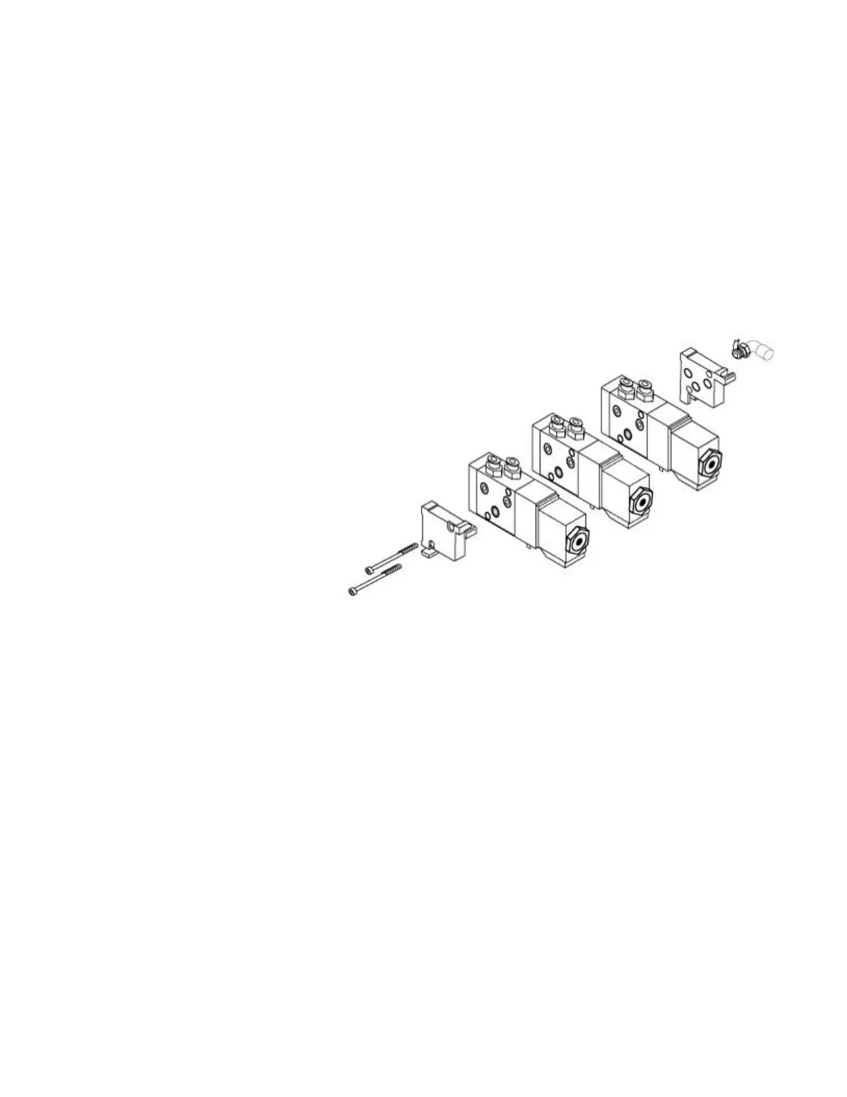
them as best as possible, then slide a screw through the left end
plate and solenoids.
Use 25 mm screws for 1 solenoid
Use 50 mm screws for 2 solenoids
Use 70 mm screws for 3 solenoids
Repeat for the second screw. Both screws should extend a
little bit out of the last solenoid.
Line up the stack screws with the holes in the right end plate and
assemble. Before tightening, align the solenoid valves so their
tops are even.
Use the screw removed in step 8 to install the left end plate to
the valve bracket. Be careful not to trap any wires behind the
plate.
Reconnect the valve box heater wires to the A1 connector.
Connect the tubing from the actuator to the new solenoid valve
by pushing it into the press fitting.
The tubing from the side of the actuator connects to the
outside fitting on the solenoid (the fitting furthest from the
electronics board, labeled 2).
Trim the tubing as needed to keep installation neat.
If installing new tubing, cut the tie-wrap around the tubing leading
from the actuator and route the tubing across the oven top to the
valve actuators.
Turn on the valve actuator air.
 Loading...


