NA (Network Analyzer) Mode 41
Measurement Selection
How to select a NA Measurement
Press Measure 1.
Then choose from the following:
o S11 1-port reflection measurement.
o S21 2-port transmission measurement. Requires Opt 110. Learn how to
make this measurement on page 49.
o More - These measurements are typically used as diagnostic tools for service
personnel.
o A Measurement of the A receiver.
o R1 Measurement of the R1 receiver.
NOTE The A and R1 receiver measurements are NOT corrected for absolute power.
They are only useful for making relative measurements. The Y-Axis and markers
are labeled in dB - NOT dBm. Specifically, R1 does NOT indicate the actual
power levels out of the source port. The actual power level is close to the typical
output power of +5 dBm (High power) and -25 dBm (Low power).
Learn more about raw receiver measurements in the FieldFox Supplemental
Online Help: www.agilent.com/find/fieldsfoxsupport
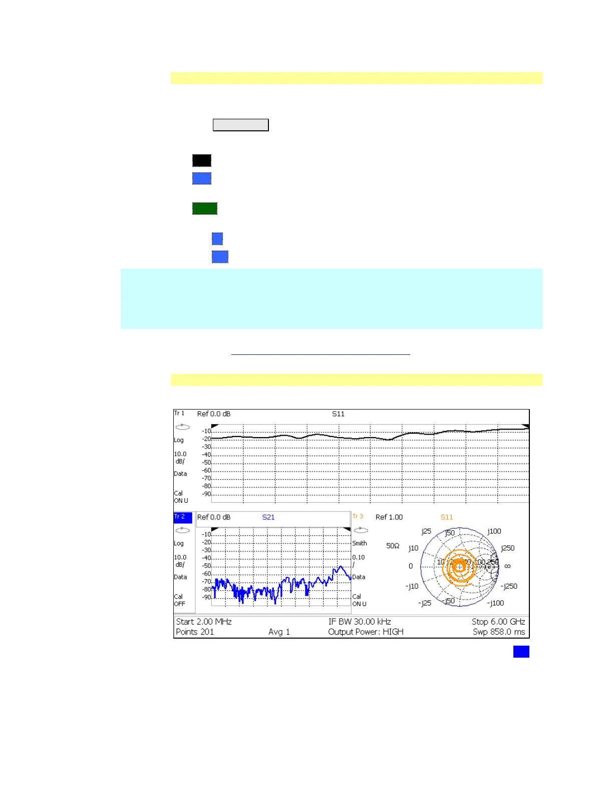
Multi-Trace Configurations
In NA Mode you can display multiple traces on the FieldFox screen.
A 3-trace configuration. Tr2 is the ACTIVE trace as indicated by the highlighted Tr 2
Trace Setting Notes
The Frequency Range, IF BW, Resolution, Average, and Output Power settings
are common for all displayed traces.
 Loading...


