60 N9912A FieldFox User’s Guide
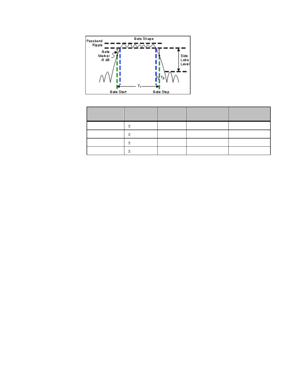
Time domain Gate Shape setting
Cutoff time is the time between the stop time (-6 dB on the filter skirt) and the
peak of the first sidelobe.
T
1
is the gate span, which is equal to the stop time minus the start time.
T
2
is the time between the edge of the passband and the 6 dB point,
representing the cutoff rate of the filter.
T
3
is the time between the 6 dB point and the edge of the gate stopband.
For all filter shapes T
2
is equal to T
3
, and the filter is the same on both sides of
the center time.
Minimum gate span is twice the cutoff time. Each gate shape has a minimum
recommended gate span for proper operation. This is a consequence of the finite
cutoff rate of the gate. If you specify a gate span that is smaller than the
minimum span, the response will show the following effects:
distorted gate shape that has no passband
distorted shape
incorrect indications of start and stop times
may have increased sidelobe levels.
 Loading...


