Rockwell Automation Publication 750-UM006C-EN-P - March 2022 171
Drive Maintenance Chapter 5
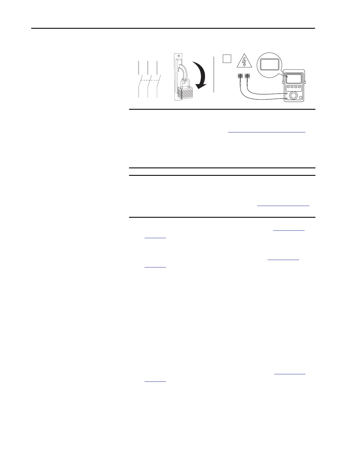
2. Remove lock out / tag out from upstream power and apply power.
3. Turn on 24V DC control power circuit breaker (#3 in Figure 10 on
page 172).
4. Verify that the HIM energizes.
5. Turn on the mechanical brake circuit breaker (#2 in Figure 10 on
page 172).
Both circuit breaker options are shown, if a source brake option is used
the breaker will have a rotary disconnect.
6. Use the HIM or PLC to verify that the brakes have properly energized.
View 07:01 [Dig In Sts] for verification. If bit 1 is equal to '1' all,
breakers are closed/energized. If bit 1 equals '0' then one of the three
breakers is open/tripped.
7. Turn on the 400/480V AC main control power (#1 in Figure 10 on
page 172).
IMPORTANT The On-Machine Drive has multiple grounding locations. Refer to the
electrical schematics for specific information about the grounding for your
specific configuration. See the Catalog Number Explanation
on page 16 for
more information about configuration type.
The safety ground, PE, must be connected to earth-grounding-system.
Some codes may require redundant ground paths and periodic examination
of connection integrity.
IMPORTANT This lock out / tag out is only for upstream power. During initial installation,
the On-Machine Drive does not have power. The breakers should be in the
OFF position when the unit arrives. Verify that all breakers are OFF before
startup is initiated. For more information, see Circuit Breakers
on page 24
section.
TIP 07:01 [Dig In Sts] should always be assigned and used as one of the
Datalinks (to the PAC Network) for remote monitoring of the brake contactor
status (Bit 0), circuit breaker status (Bit 1), and the P0 & P1 status
(bits 2,3,4,5).

 Loading...


