EasyManuals Logo

Allen-Bradley The PowerFlex 755 On-Machine User Manual

Allen-Bradley The PowerFlex 755 On-Machine
218 pages
To Next Page IconTo Next Page
To Previous Page IconTo Previous Page
Page #172 background imageLoading...
Page #172 background image
172 Rockwell Automation Publication 750-UM006C-EN-P - March 2022
Chapter 5 Drive Maintenance
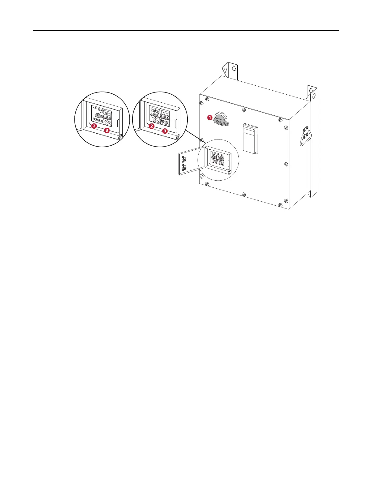
Figure 10 - Circuit Breaker Identification
1. 400/480V AC rotary power for main circuit breaker (140G-G6C3-C30-AJ).
2. 24V DC mechanical brake circuit breaker (1489-M2D040) is shown on the enclosure.
The 400/480V AC source mechanical brake circuit breaker (140M-C2E-B25/140MT-C3E-B25) is shown on the left.
3. 24V DC control power circuit breaker (1489-M2D2040).
8. Run the drive and test performance, if the Frame 2 drive was replaced,
you must follow the startup procedure to recommission the drive.

Table of Contents

Questions and Answers:

Question and Answer IconNeed help?

Do you have a question about the Allen-Bradley The PowerFlex 755 On-Machine and is the answer not in the manual?

Allen-Bradley The PowerFlex 755 On-Machine Specifications

General IconGeneral
BrandAllen-Bradley
ModelThe PowerFlex 755 On-Machine
CategoryDC Drives
LanguageEnglish

Related product manuals