iPAM400 – Product Manual
U-0629-0171.doc – Issue: 04 complete, approved
Page 10 of 138
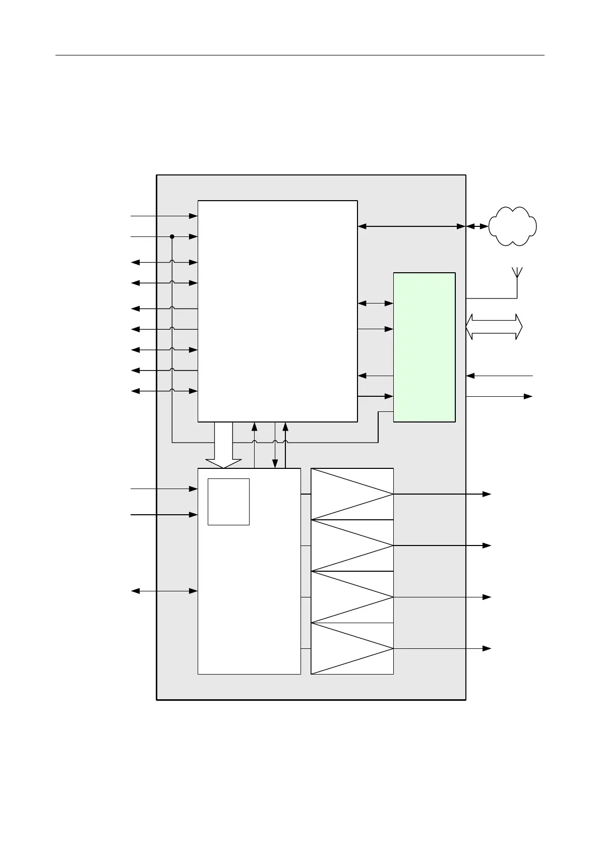
2 Functional Description
The iPAM400 is functionally split into four main blocks as shown in Figure 2.
Figure 2 iPAM400 block diagram
CONTROLLER
AUDIO IN
AUX
CONTROL
MODULE
(*)
GSM-R/DTMF/
AUDIO
EXPANSION
LANETHERNET
AUX AUDIO IN
(ASL PAGING
MICROPHONE OR
OTHER SOURCE)
ASL MICROPHONE
OR BMB01 COMMS
COMMISSIONING
LAPTOP
AMPLIFIERS
AUDIO OUT
(4x)
OR
PERIPHERALS
VGA DISPLAY
(*): Aux Control Module is optional and provides expansion options: GSM-R interface (future option), DTMF interface (future option), or
Audio Expansion.
ANS: ASL Ambient Noise Sensor
BMB01: ASL Remote I/O Unit
CAN = Controller Area Network
DTMF = Dual-Tone Multi-Frequency
GSM-R = Global System for Mobile communications - Railway
GSM-R
DTMF
RS232
DC POWER
iPAM400
POWER FOR
ASL MICROPHONE,
BMB01, OR ANS
DC POWER
RS485
RS485
DC POWER
AUDIO IN
RS232/USB
VGA
USB (2x)
100 V AUDIO OUT
100 V AUDIO OUT
100 V AUDIO OUT
100 V AUDIO OUT
AMPLIFIER
MOTHERBOARD
230V AC
MAINS
OR
2 x AUDIO IN
(from DTMF interface)
AUDIO I/O
(from/to AUDIO
EXPANSION)
4 x AUDIO OUT
RS232
(TTL)
AUDIO IN (LISTEN-IN)
POWER
SUPPLY
24V DC
CAN/RS485
(FOR ASL USE)