iPAM400 – Product Manual
U-0629-0171.doc – Issue: 04 complete, approved
Page 108 of 138
8.11 iPAM400 Mainframe Replacement
Removing the Old Amplifier Mainframe:
1. Remove the iPAM400 front panel; see Section “8.1 Removing the Front Panel” (page 99).
2. Power the mainframe off; see Section “8.2 Powering the Mainframe Off” (page 100).
3. Remove the mainframe from the rack; see Section “8.8 Removing the Mainframe from the Rack”
(page 105).
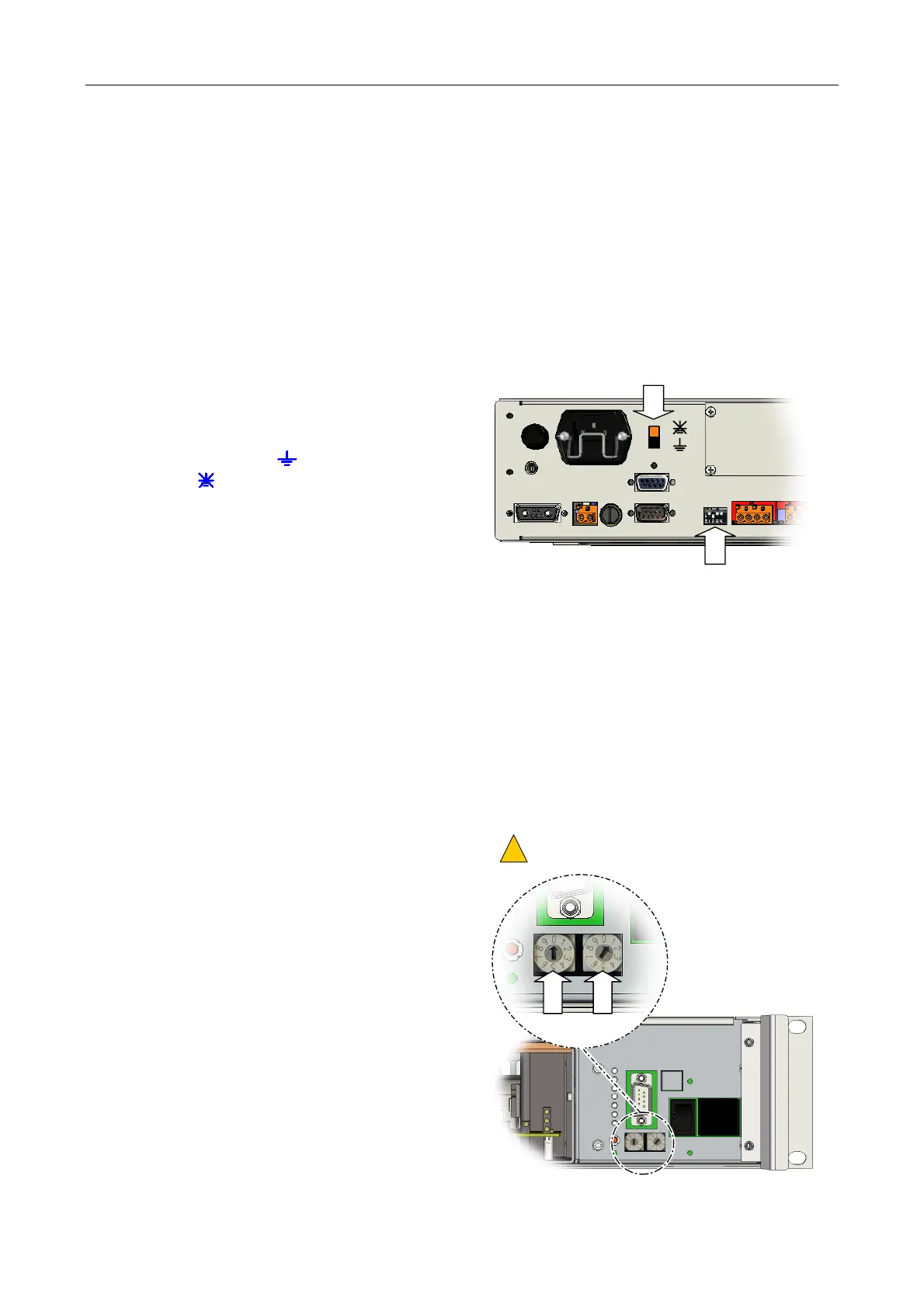
4. Make a note of the Earth Lift switch setting.
This switch is located on the rear panel (to the
right of the IEC connector), and can either be
in the grounded (
) or the ground-lift
position (
).
5. Make note of the Mode DIP switches settings.
These switches are located on the rear panel
(to the left of SLOT 4 Wago connectors).
EARTH LIFT
MODE DIP SWITCHES
6. If the iPAM400 is to be returned to ASL for repair or service, then it should be properly packed to
prevent physical and ESD damage.
Advice on packing the product for return can be provided by ASL.
Installing the New Mainframe:
1. Remove the front panel from the new iPAM400; see Section “8.1 Removing the Front Panel”
(page 99).
2. Ensure that the Mainframe Address switches
are set to address ‘01’.
These switches are located on the front of the
mainframe (to the right of the mains and
battery isolation switches).
ROTARY SWITCHES SET TO ‘01’.
OTHER ADDRESSES ARE FOR ASL USE ONLY.
!
!
O
I
0
1