iPAM400 – Product Manual
U-0629-0171.doc – Issue: 04 complete, approved
Page 28 of 138
4.2 Installation Requirement
4.2.1 Equipment and Tool Requirements
• The iPAM400 Amplifier Mainframe.
• MX100, MX200, or MX400 amplifier modules as specified in your system design documentation.
• A mainframe front panel to suit the amplifier configuration.
• Cabling as specified in Section “4.2.2 External Cabling Requirements” (page 29) to suit your system
design.
• A small flat-bladed screwdriver.
• Pozidriv screwdrivers (No 1 and No 3).
• A pair of wire cutters/strippers.
• A 19-inch standard rack fitted with supporting rails and wired with power supply, signal, and control
wiring, as required by your specific system design.
!
!
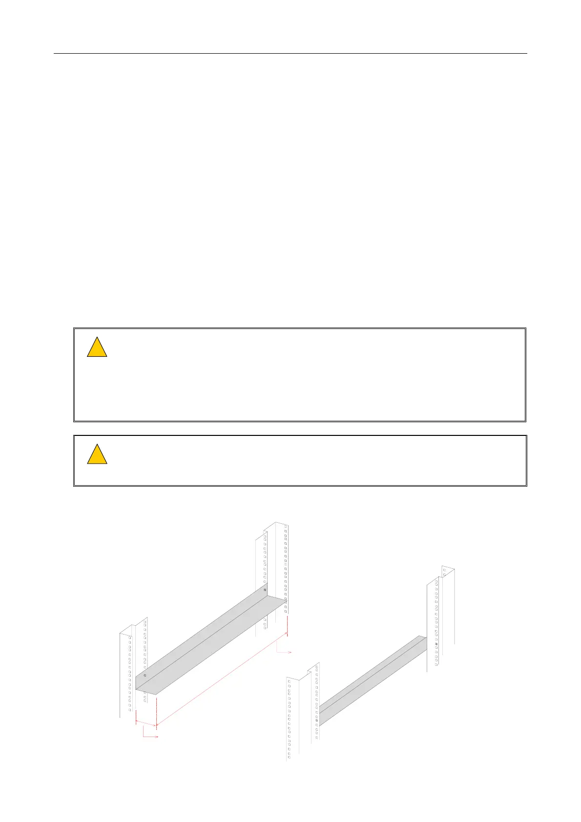
1) Ensure that the supporting rails extend at least 425 mm (mainframe depth) into the
rack and between 40 mm and 50 mm under the mainframe in order not to block the
ventilation holes, yet to prevent the mainframe from twisting and falling between the
supports; see details in Figure 5.
2) The supporting rails must be capable of safely bearing the weight of the equipment
(max. 20 kg).
!
!
If the iPAM400 is intended to be table or shelf mounted, i.e. not in a 19-inch standard rack,
then the unit should always be fitted into a 19-inch desk case or flight case. This is to
prevent ingress of dust or debris that may otherwise occur over a period of time.
Figure 5 19-inch rack with supporting rails (example)
FRONT OF RACK
LEFT-HAND SIDE
SUPPORTING
RAIL
RIGHT-HAND SIDE
SUPPORTING
RAIL
MINIMUM WIDTH = 40 mm
MAXIMUM WIDTH = 50 mm
MINIMUM DEPTH = 425 mm
(Rack and supporting rail design are example only.)