iPAM400 – Product Manual
U-0629-0171.doc – Issue: 04 complete, approved
Page 43 of 138
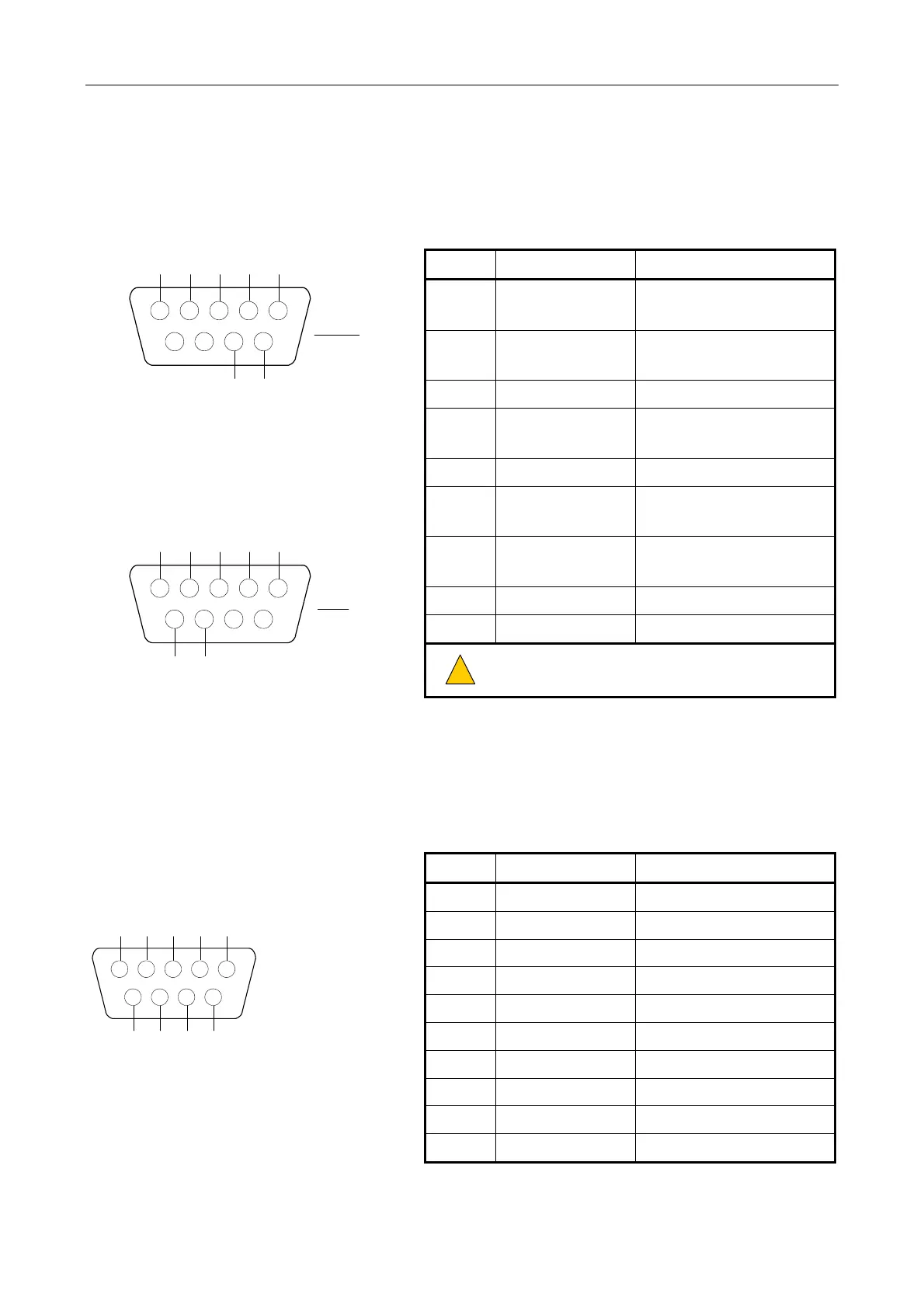
5.1.7 Audio-CAN Bus / RS485 Port: STATUS PORTS
1 2 3 4 5
6 7 8 9
RS485DXN
CAN_L
GND
AUDIO MON-
AUDIO MON+
RS485DXP
CAN_H
AUDIO MON-
GND
AUDIO MON+
RS485DXP
CAN_H
6789
5 4 3 2 1
RS485DXN
CAN_L
FEMALE
MALE
Dual 9-way D connector
(female/male)
Pin No Signal Description
1 RS485DXN
Data–
(EIA RS485 9600 baud)
2 CAN_L
Controller Area Network
(Low)
3 GND 0 V Reference
4 AUDIO MON-
Audio Monitor Bus
–10 dBu nominal
5 AUDIO MON+ As above
6 RS485DXP
Data+
(EIA RS485 9600 baud)
7 CAN_H
Controller Area Network
(High)
8, 9 N/C Not connected
Shell Screen For cable screen
!
!
These connectors are for ASL use only (for
software debug and configuration purposes).
5.1.8 RS232 Port
1 2 3 4 5
6 7 8 9
DCD
RXD
TXD
DTR
GND
DSR
RTS
CTS
RI
Standard 9-way
D connector
(male)
Linux reference:
• RS232 port = ttyS0 port
Pin No Signal Description
1 DCD Carrier Detect
2 RXD RS232 Received Data
3 TXD RS232 Transmitted Data
4 DTR Data Terminal Ready
5 GND Common Ground
6 DSR Data Set Ready
7 RTS Request To Send
8 CTS Clear To Send
9 RI Ring Indicator
Shell Screen For cable screen