iPAM400 – Product Manual
U-0629-0171.doc – Issue: 04 complete, approved
Page 42 of 138
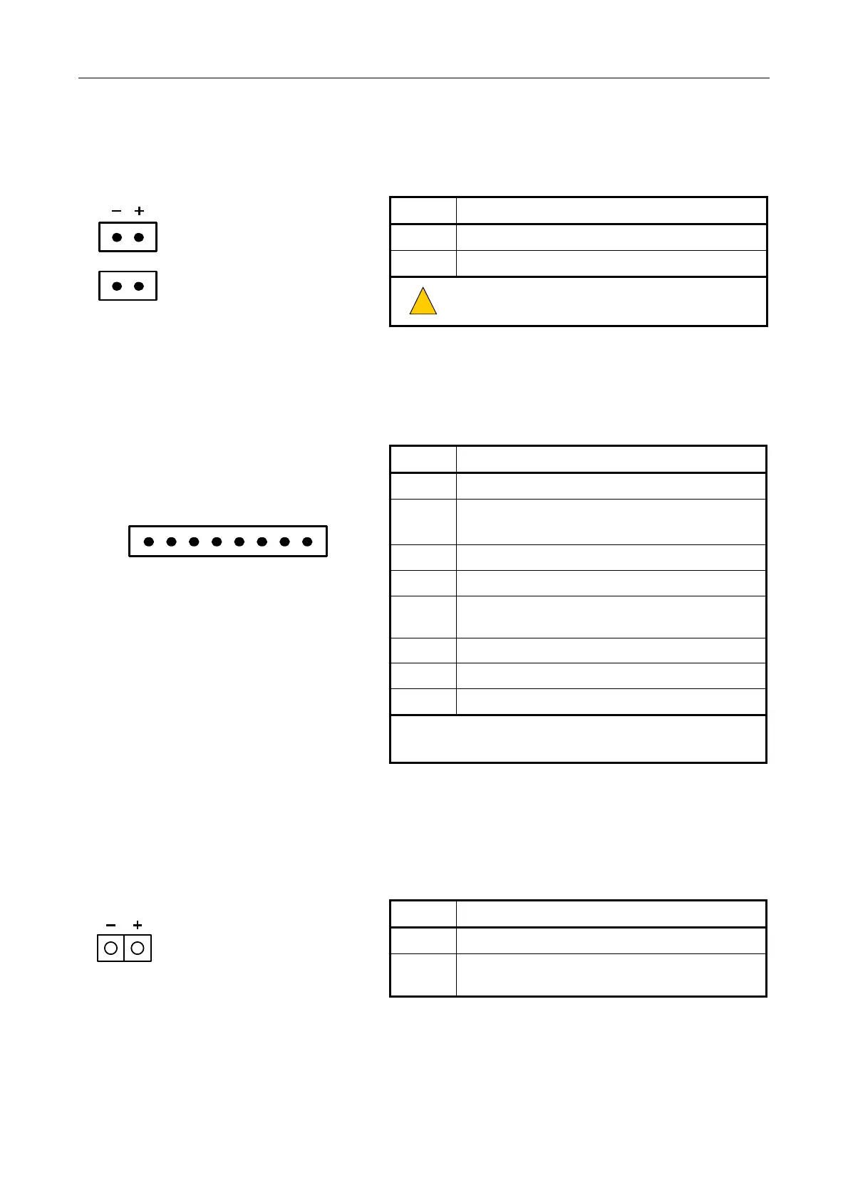
5.1.4 100 V Line Standby Input: STANDBY IN
2 x 2-way pluggable
Wago cage clamp terminal
(5.08 mm)
(male)
Signal Description
−
100 V line audio circuit from standby amplifier
+
As above
!
!
Ensure +/- phase is preserved.
5.1.5 Audio In/RS485 Ports: INPUT 1 and INPUT 2
SCRN
IN+
IN−
0V
+V
DXP
DXN
SCRN
8-way pluggable
Wago cage clamp terminal
(3.81 mm)
(male)
Linux reference:
• INPUT 1 = ttyUSB0 port
• INPUT 2 = ttyUSB1 port
Signal Description
SCRN For cable screen
IN+
Balanced audio input +ve level
0 dBu / 10 kΩ / -20 dBu max. sensitivity
IN- As above but –ve level
0V 0 V supply
+V
+V supply output (18-36 V depending on AC or DC
supply, and battery conditions) / 500 mA max
DXP Data+ (EIA RS485 19200/9600 baud)
1)
DXN Data– (EIA RS485 19200/9600 baud)
1)
SCRN For cable screen
1) Microphone: 19200 baud
BMB01: 9600 baud
5.1.6 Auxiliary DC Output: AUX OUT
2-way pluggable
Wago cage clamp terminal
(5.08 mm)
(female)
Signal Description
−
0 V supply
+
+V auxiliary DC output (21-38 V depending on AC or
DC supply, and battery conditions) / 1 A fuse