iPAM400 – Product Manual
U-0629-0171.doc – Issue: 04 complete, approved
Page 46 of 138
5.2 Connection Diagrams
The following diagrams show examples of the connection of an ASL BMB01 Remote I/O Unit, ANS Sensors,
and Paging Microphones to the iPAM400.
5.2.1 Microphone Connection
The following diagrams show examples of connection of ASL microphones to the iPAM400:
• DMS Paging Microphone: see Figure 16 (page 46).
• SAP02 Station Announcement Point: see Figure 17 (page 47).
• RRM02 Remote Radio Microphone: see Figure 18 (page 47) for single microphone connection. Refer to
the RRM02 user documentation for multiple microphone connection; see Table 7 (page 132).
• Other microphones including radio and application specific microphones: refer to the appropriate
microphone’s user documentation or to ASL.
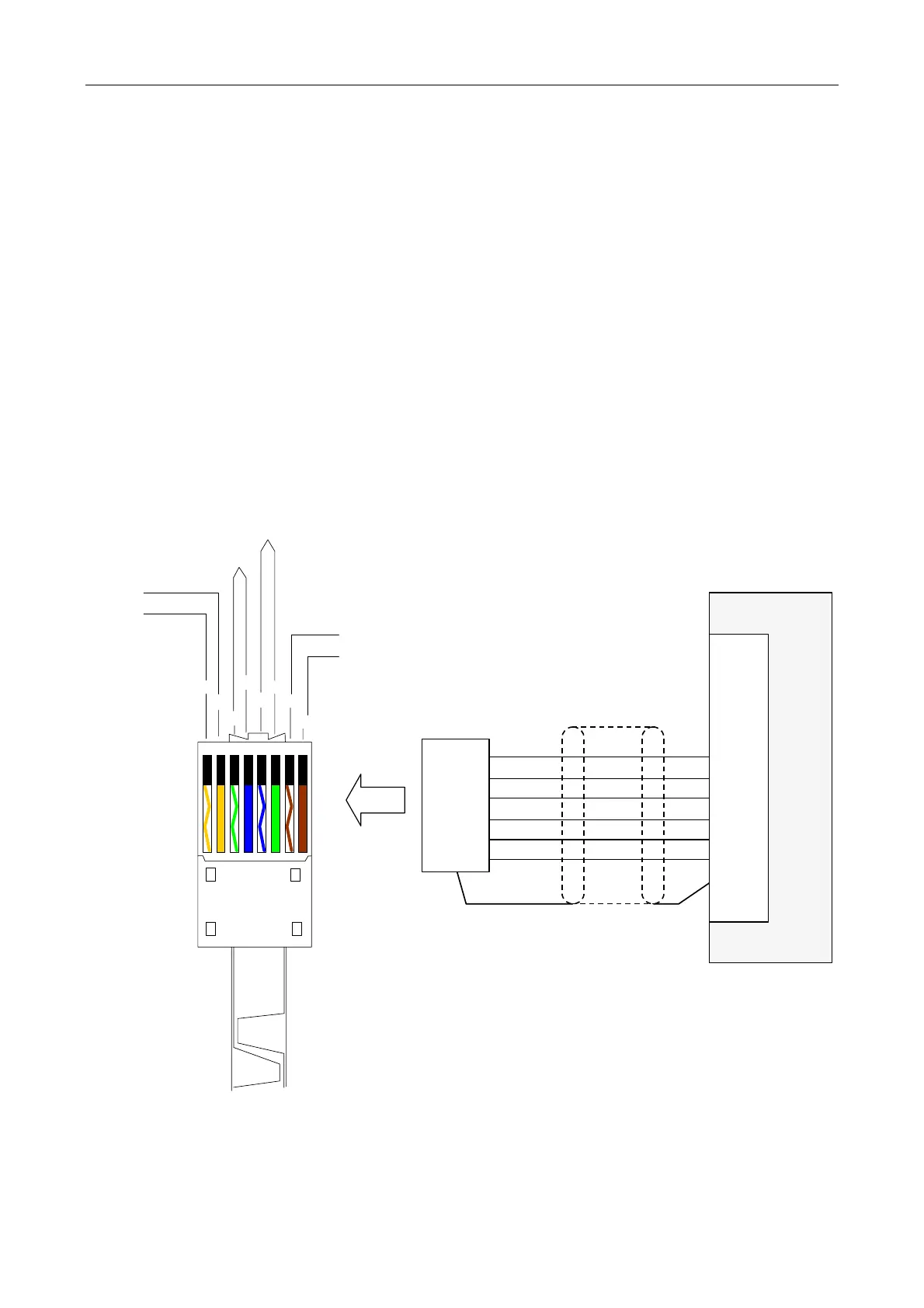
Figure 16 DMS microphone connection
iPAM400
AUDIO+
AUDIO-
0Vin
+SUPPLY
DATA DXP
DATA DXN
INPUT 1
or
INPUT 2
SCRN
IN+
IN-
0V
+V
DXP
DXN
SCRN
MICROPHONE
CABLE CONNECTOR
(DMS5/10/20)
CONNECTOR SHELL
AUDIO +
AUDIO -
0V
+SUPPLY
DATA DXP
DATA DXN
12345678
W/O
O
W/G
BL
W/BL
G
W/BR
BR
(Pin 1)
(Pin 2)
(Pins 3,4)
(Pins 5,6)
(Pin 7)
(Pin 8)
RJ45
(
See Note 1
)
Notes (Figure 16):
1) Refer to the user documentation specific to the DMS microphone being used for details; see Table 7
(page 132).
2) Refer to Section “6.1 Generating a Configuration File” (page 59) for configuration details.