iPAM400 – Product Manual
U-0629-0171.doc – Issue: 04 complete, approved
Page 53 of 138
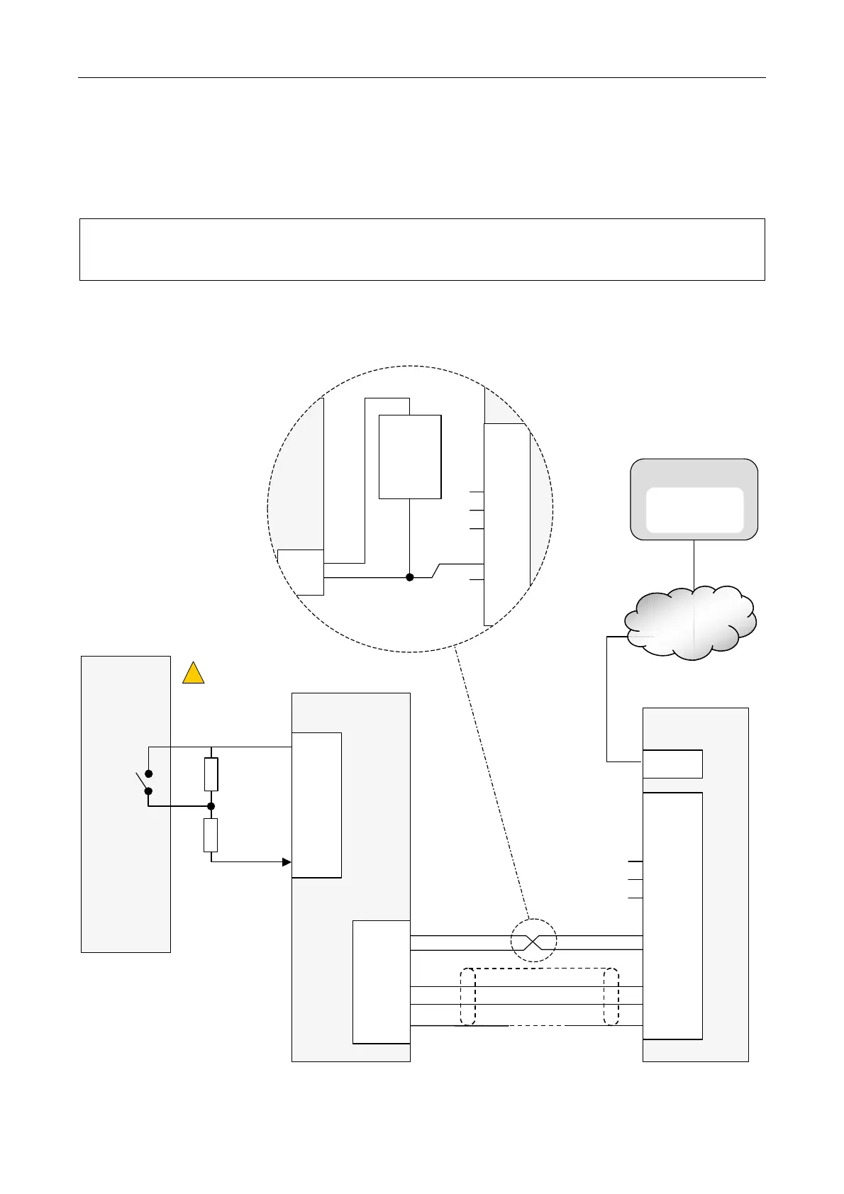
5.2.2.3 BMB01 and Monitored Fault Input Connection for Third-Party Equipment Fault Monitoring
The BMB01 analogue inputs can be used for fault inputs from other equipment where the fault wiring is
monitored by the iPAM400.
Only the analogue inputs of the BMB01 can support resistively monitored fault inputs.
This is the preferred fault monitoring method, because any cable faults will be reported.
Figure 21 BMB01 fault input contact connection (monitored) (example)
IP NETWORK
INPUT 1
or
INPUT 2
SCRN
IN+
IN-
0V
+V
DXP
(Pin 49)
(Pin 48)
LOCAL
ISOLATED
SUPPLY
+
+24Vin
0Vin
BMB01
iPAM400
BMB01 POWERED BY EXTERNAL POWER
SUPPLY
(ALTERNATIVE TO POWER FROM
iPAM400 SHOWN BELOW)
THIRD-PARTY
EQUIPMENT
BMB01
0Vout
AI
y
CONTROL SYSTEM
THIRD-PARTY EQPT.
FAULT + CABLING
FAULT
iPAM400
+24Vin
0Vin
DATA DXP
DATA DXN
SCREEN
(Pin 52)
(Pin 51)
(Pin 50)
(Pin 49)
(Pin 48)
INPUT 1
or
INPUT 2
SCRN
IN+
IN-
0V
+V
DXP
DXN
SCRN
ANALOGUE I/P
(Pin 1)
ETHERNET
(
See Notes 2 and 3
)
470 Ω
6k8 Ω
(
See Notes 2 and 3
)
(
See Warnings 1 and 2
)
!
!
(
See Note 1
)