iPAM400 – Product Manual
U-0629-0171.doc – Issue: 04 complete, approved
Page 124 of 138
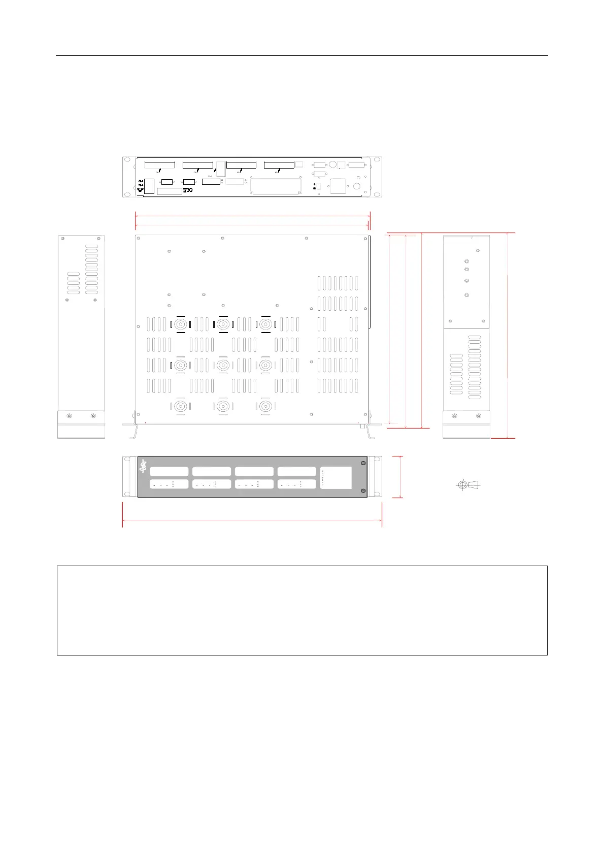
10 Mechanical Dimensions
Figure 25 Mechanical dimensions
408 mm
419 mm
439 mm
86 mm
Front panel shown fitted (4 x MX100 configuration shown as example.)
(Connectors, blankin
and fixin
plates, fuse, and screws not shown on rear panel.)
425 mm (including max dimension of connectors, fuse, screws, etc.)
iPAM400
-0dB
-20dB
-40dB
100W
-0dB
-20dB
-40dB
100W
-0dB
-20dB
-40dB
100W
-0dB
-20dB
-40dB
100W
fault
sync
processor
ethernet
aux
battery
mains
Modular Power Amplifier
THIRD ANGLE PROJECTION
approx 487 mm (including handles)
approx 458 mm (including handles)
436 mm
faultselectsupply faultselectsupply fau ltselectsupply faultselectsupply
1) ASL recommend a rear clearance depth of at least 110 mm for cabling.
A 19-inch standard rack with 600 mm depth provides the required room for installation
including the rear cabling.
2) In order for customers to produce their own site documentation drawings of the front and
rear panel are available from ASL.