iPAM400 – Product Manual
U-0629-0171.doc – Issue: 04 complete, approved
Page 41 of 138
5.1 Terminal Allocation
All connector views looking into the rear of the iPAM400.
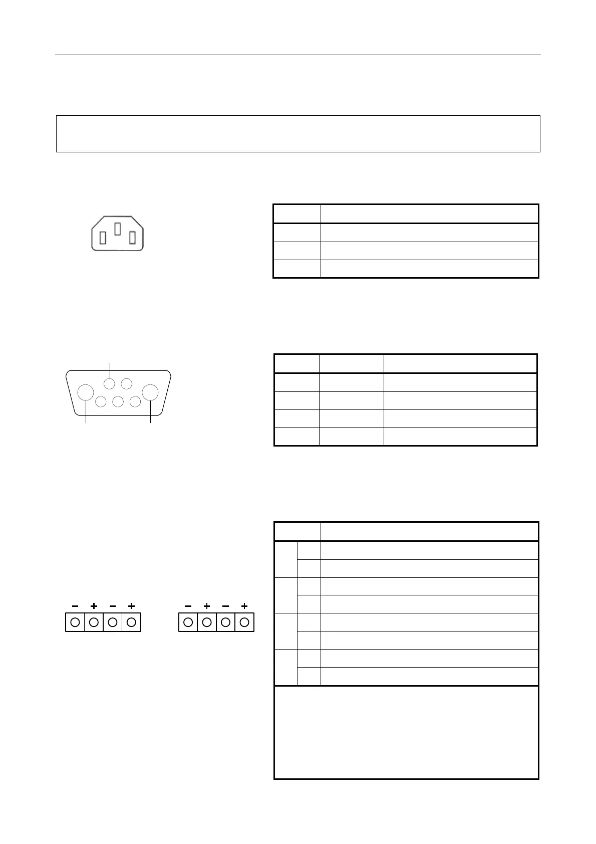
5.1.1 AC Mains Inlet
L E N
IEC320 plug
Signal Description
L Live (European standard: 230 V, 50 Hz, +/–10%)
E Earth
N Neutral (European standard: 230 V, 50 Hz, +/–10%)
5.1.2 DC Supply Input: BATTERY IN
1 2
GND
3 4 5
BATTERY +
A1 A2
BATTERY -
7W2 mixed signal
D connector
(male)
Pin No Signal Description
A1 BATTERY+ DC supply (21-27.6 V)
A2 BATTERY- As above
1 GND Ground
2 to 5 N/C Not connected
5.1.3 100 V Line Outputs: SLOT 1, SLOT 2, SLOT 3, and SLOT 4
D C B A
2 x 4-way pluggable
Wago cage clamp terminal
(5.08 mm)
(female)
Signal Description
−
100 V line audio output to loudspeaker circuit A
A
+
As above
−
100 V line audio output to loudspeaker circuit B
B
+
As above
−
100 V line audio output to loudspeaker circuit C
C
+
As above
−
100 V line audio output to loudspeaker circuit D
D
+
As above
1) A and B outputs support loudspeaker line
monitoring using AC line surveillance with
ASL AEL01/AEL02 Active End of Line Device
2) C and D outputs do not support loudspeaker
line monitoring using AC line surveillance with
ASL AEL01/AEL02.
3) All outputs support DC line surveillance.