iPAM400 – Product Manual
U-0629-0171.doc – Issue: 04 complete, approved
Page 25 of 138
Mainframe Controls
These controls are only accessible by removing the front panel. This is to prevent inadvertent or
unauthorised disablement of the unit.
Control Function
3
Mains Isolation
Switch
This switch connects or disconnects AC mains power to or from the unit.
4
Battery Isolation
Switch
This switch connects or disconnects DC power to or from the unit.
!
!
Under normal circumstances these isolation switches will be left in the ON position.
Both the mains and the battery isolation switches should be switched off in order to disconnect power from
the mainframe, for example when an amplifier module is to be inserted or removed.
5
Mainframe
Address Switches
These rotary switches are for ASL use only.
User must always set address to ‘01’.
6
Reset/Shut Down
Button
Recessed button. This is used to reset or to shut down the iPAM400 as follows:
• Short press (< 1 second)
Starts up the iPAM400 application (if previously shut down), or shuts it down (if
previously running). See processor LED.
• Press of > 5 seconds at any time
Causes an instant iPAM400 application power-down.
!
!
It is recommended that the iPAM400 application be shut down using the Reset/Shut Down button before
power is disconnected from the iPAM400 using the mains and battery isolation switches.
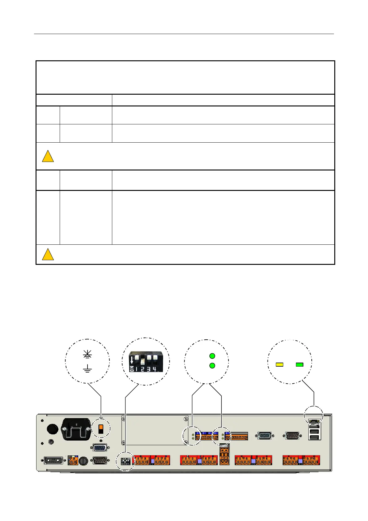
3.2 Rear Panel Indicators and Controls
1
3 4
2
RS485 PORT
STATUS INDICATORS
ETHERNET PORT
STATUS INDICATORS
activit
link
R
T
EARTH LIFT SWITCH MODE DIP SWITCH