iPAM400 – Product Manual
U-0629-0171.doc – Issue: 04 complete, approved
Page 55 of 138
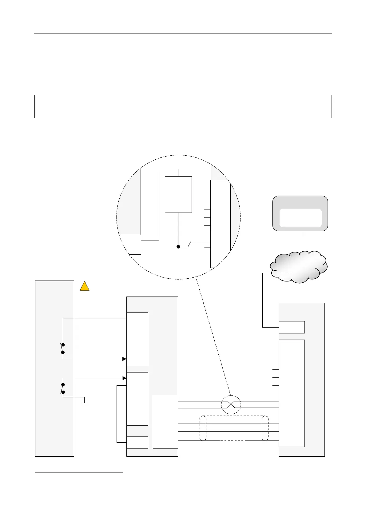
5.2.2.4 BMB01 and Non-Monitored Fault Input Connection for Third-Party Equipment Fault Monitoring
Either digital or analogue inputs
1
of the BMB01 can be used for non-monitored fault inputs. The following
diagrams show examples of connection of digital and analogue inputs to third-party equipment.
When the fault input wiring is not monitored then a fault in the wiring may prevent an
equipment fault from being reported.
Figure 22 BMB01 fault input contact connection (non-monitored) (example)
THIRD-PARTY
EQUIPMENT
BMB01
0Vout
AI
y
+24V0ut
(Pin 26)
IP NETWORK
CONTROL
SYSTEM
THIRD-PARTY EQPT.
FAULT
iPAM400
+24Vin
0Vin
DATA DXP
DATA DXN
SCREEN
(Pin 52)
(Pin 51)
(Pin 50)
(Pin 49)
(Pin 48)
INPUT 1
or
INPUT 2
SCRN
IN+
IN-
0V
+V
DXP
DXN
SCRN
DI
y
-
DI
y
+
DIGITAL I/P ANALOGUE I/P
OR
(Pin 1)
ETHERNET
(
See Notes 2 and 3
)
(
See Notes 2 and 3
)
(
See Warnings 1 and 2)
!
!
INPUT 1
or
INPUT 2
SCRN
IN+
IN-
0V
+V
DXP
(Pin 49)
(Pin 48)
LOCAL
ISOLATED
SUPPLY
+
+24Vin
0Vin
BMB01
iPAM400
BMB01 POWERED BY EXTERNAL POWER
SUPPLY
(ALTERNATIVE TO POWER FROM
iPAM400 SHOWN BELOW)
(
See Note 1
)
1
Non-monitored analogue input is not implemented in the iPAM400 application at the time of publication of this document.