iPAM400 – Product Manual
U-0629-0171.doc – Issue: 04 complete, approved
Page 106 of 138
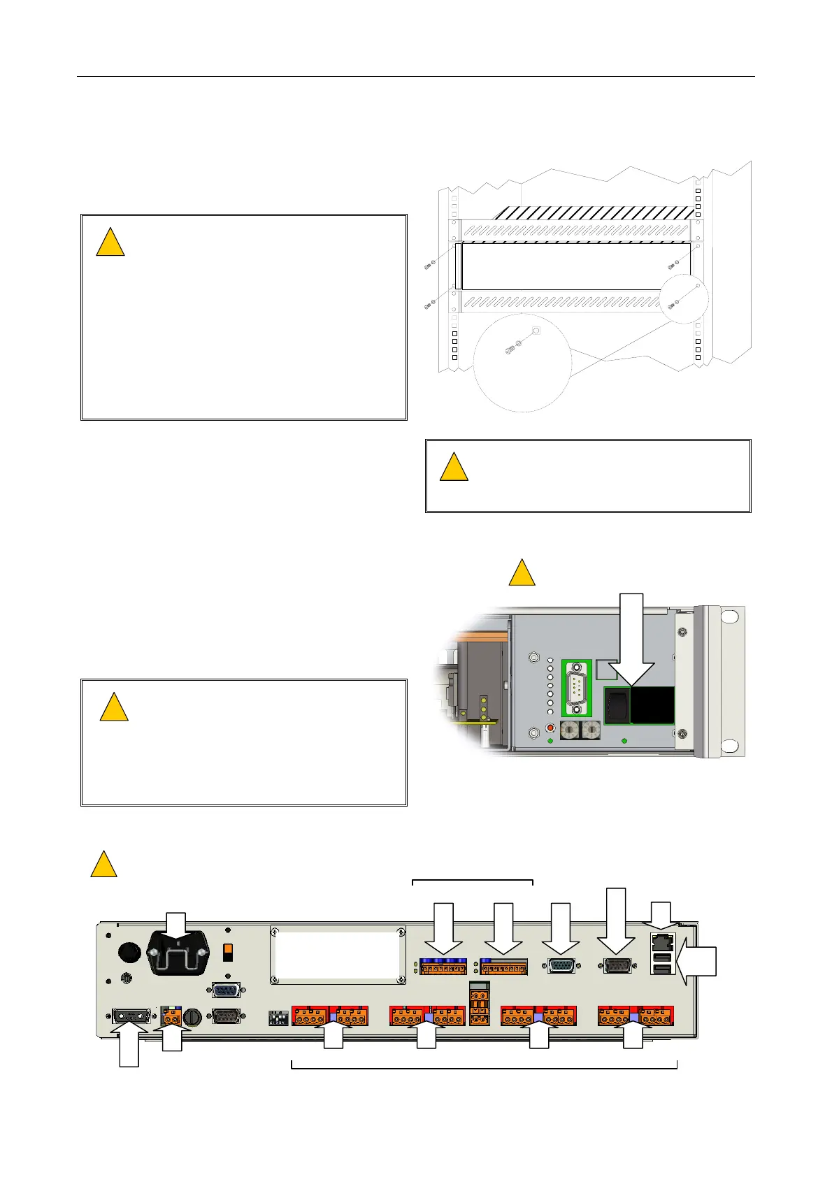
8.9 Installing a Mainframe into the Rack
1. Fit the mainframe into the rack and secure it
using the 4 x M6 Pozidriv screws.
!
!
This equipment is heavy (max. 20 kg).
Please lift and handle with care to avoid
strain or impact injuries.
Do not use the handles to lift or carry
the mainframe. The handles are
designed for sliding the unit into and
out of the equipment rack, and not to
support its weight. Use the underside
edges of the mainframe to lift and carry
it.
GENERIC 19-INCH 2U FORMAT
M6 POZIDRIVSCREW
M6 PLAIN WASHER
M6 CAGE NUT
2. Insert the amplifier modules into the required
slots; see Section “8.4 Installing an Amplifier
Module into the Mainframe” (page 102).
!
!
Take care to ensure that the amplifier
modules are installed into the slots they
occupied in the original mainframe.
3. Ensure that the mainframe AC mains and
battery isolation switches are turned off.
4. Ensure that the AC mains supply to the unit is
isolated.
5. Ensure that the DC supply to the unit is
isolated, if used.
!
!
External 24 V DC batteries when
connected to this unit can deliver very
high currents that could cause fire or
burns. Take care to avoid short circuits
of the battery supply by tools or
jewellery.
(Front panel removed)
BATTERY AND AC MAINS ISOLATION
SWITCHES: OFF
!
!
O
I
6. Connect the field wiring. Connect the power supply cabling last.
AUDIO IN/RS485 PORTS
SLOT 4
SLOT 3
SLOT 2 SLOT 1
INPUT 2
RS232
INPUT 1
AC INLET
ETHERNET
USB
100
V LINE OUTPUTS
VGA
1
2
AUX OUT
BATTERY IN
ENSURE THAT THE AC MAINS CABLE IS SECURED
WITH THE RETAINING CLIP IN ORDER TO PREVENT
ACCIDENTAL REMOVAL.
!
!
OPTIONAL MODULE CAN BE FITTED:
• AUDIO EXPANSION I/O MODULE
• GSM-R INTERFACE MODULE
• DTMF INTERFACE MODULE