iPAM400 – Product Manual
U-0629-0171.doc – Issue: 04 complete, approved
Page 57 of 138
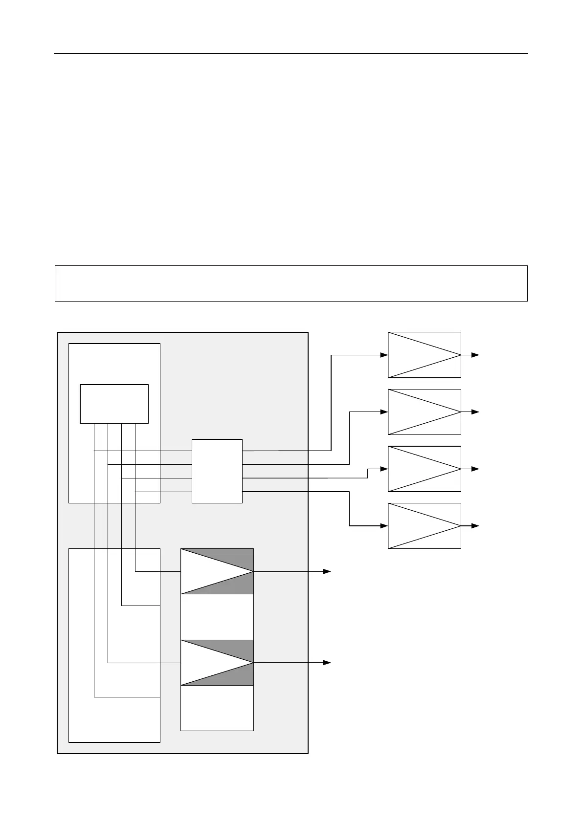
5.3 Connection of External Amplifiers
The low level outputs on the optional Audio I/O Expansion Module enables the connection of external
amplifiers to the iPAM400; see example in Figure 23. These low level outputs are paralleled with the
internal feeds to the amplifier slots and can be used to:
1) Add extra power to a zone by fitting an external amplifier in parallel.
In Figure 23 external amplifier #01 is paralleled with MX200 fitted into slot 1, and external amplifier
#03 is paralleled with MX200 fitted into slot 3.
2) Add extra zones when all the slots in the iPAM400 are occupied.
In Figure 23 external amplifiers #02 and #04 are connected to low level outputs which are not used by
amplifiers fitted into the mainframe.
External amplifiers are not monitored by the iPAM400.
Figure 23 External amplifier connection (example)
CONTROLLER
AMPLIFIERS
iPAM400
SLOT 1 - MX200
SLOT2
(OCCUPIED BY MX200)
SLOT 3 - MX200
SLOT 4
(OCCUPIED BY MX200)
AMPLIFIER
MOTHERBOARD
LOW LEVEL AUDIO
OUTPUT INTERFACE
LOW LEVEL AUDIO
EXTERNAL
AMPLIFIER
EXTERNAL
AMPLIFIER
EXTERNAL
AMPLIFIER
ZONE 1
ZONE 3
EXTRA
AMPLIFIER
ON ZONE 1
EXTRA
ZONE 2
EXTRA
ZONE 4
AUDIO I/O
EXPANSION
MODULE
(OPTIONAL)
#01
#02
#04
100 V AUDIO
OUT
100 V AUDIO
OUT
OUT 4
OUT 3
OUT 2
OUT 1
EXTERNAL
AMPLIFIER
EXTRA
AMPLIFIER
ON ZONE 3
#03
OUT 4
OUT 3
OUT 2
OUT 1