iPAM400 – Product Manual
U-0629-0171.doc – Issue: 04 complete, approved
Page 27 of 138
4 Installation
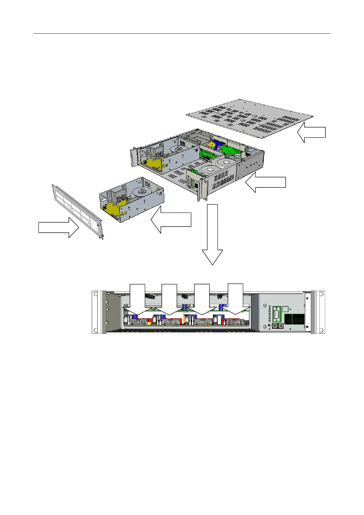
4.1 Main Components
FRONT PANEL
LID
MAINFRAME
AMPLIFIER
MODULE
MX200 200 W Amplifier Modules shown as an example: one fitted into the iPAM400 mainframe and one outside it.
The lid is supplied fitted, and is not normally removed. It is only shown removed here in order to enable the iPAM400’s
internal construction to be seen.
The iPAM400 is desi
ned to use the MX Series Amplifier Modules, and is not compatible with the M100, M200, and M400
M Series Amplifier Modules. These two series of amplifier modules are electrically identical, but have different mechanics
and connectors.
SLOT 1
AMPLIFIER MODULE SLOTS
SLOT 2
SLOT 3
SLOT 4