iPAM400 – Product Manual
U-0629-0171.doc – Issue: 04 complete, approved
Page 112 of 138
8.13.2 iPAM400 Internal Fuses
The iPAM400 supply to the amplifier modules is divided into two halves. One half feeds amplifier slots
1 and 2, the other slots 3 and 4. Each half is protected by a fuse, which can be replaced as follows.
Replacing iPAM400’s Internal Fuses:
1. Remove the iPAM400 front panel; see Section “8.1 Removing the Front Panel” (page 99).
2. Power the mainframe off; see Section “8.2 Powering the Mainframe Off” (page 100).
3. Remove the mainframe from the; see Section “8.8 Removing the Mainframe from the Rack” (page
105).
4. Remove the mainframe lid; see Section “8.7 Removing the Mainframe Lid” (page 104).
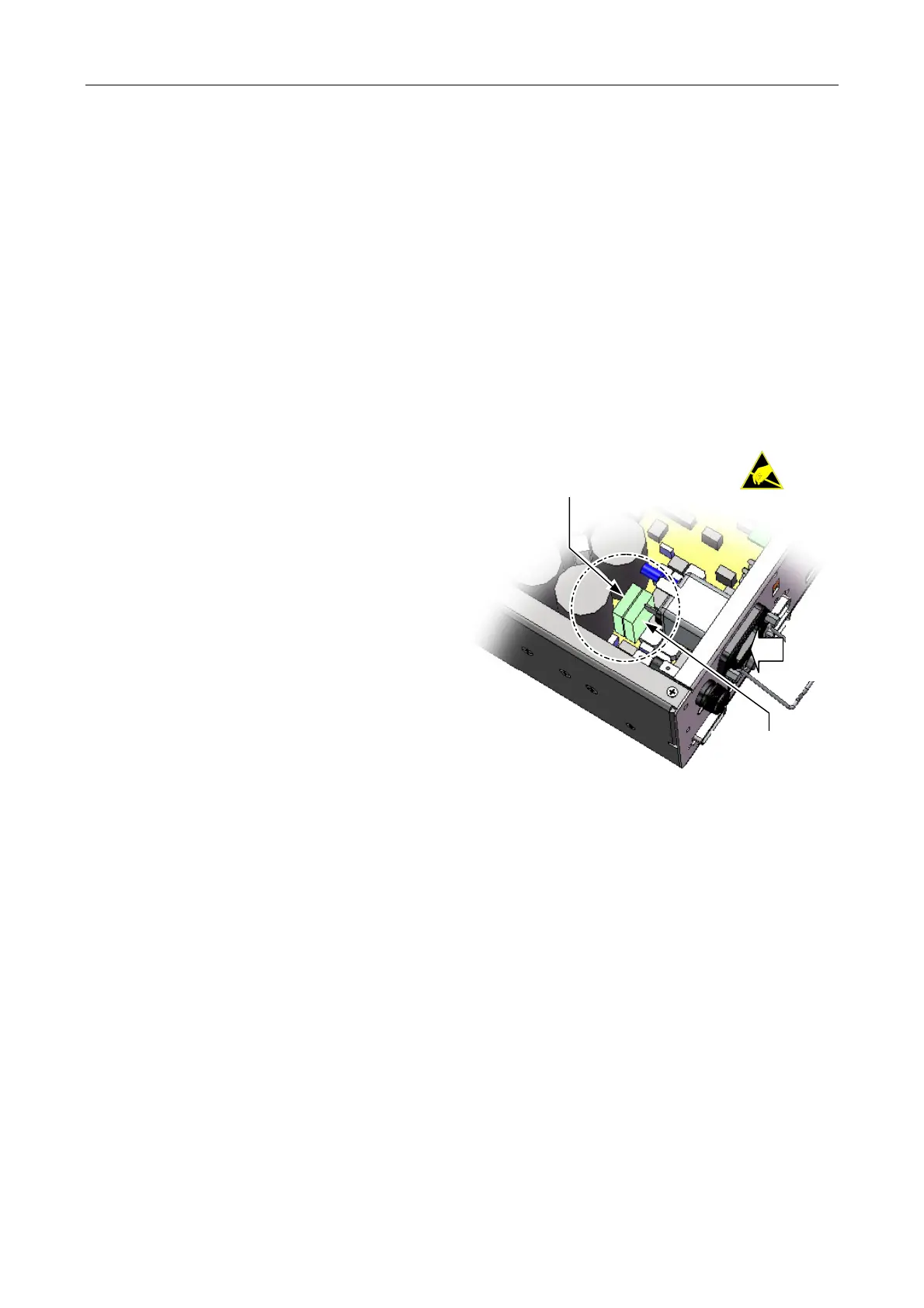
5. The two fuses are located on the amplifier
motherboard close to the AC mains inlet
located on the rear panel of the unit.
6. Inspect the fuses. If blown, then replace with
type 25 A TAC ATO 58 V; find spare in
Table 6 (page 116).
(Internal wiring
not shown for clarity.)
AC
MAINS
INLET
AMPLIFIER SLOTS
3 AND 4
AMPLIFIER SLOTS
1 AND 2
(FUSE TYPE: 25 A TAC ATO 58 V)
7. Re-fit the mainframe lid, and secure it in position using the 14 x M3 Pozidriv screws.
8. Re-fit the mainframe into the rack; see Section “8.9 Installing a Mainframe into the Rack” (page 106).
9. Power the mainframe on; see Section “8.5 Powering the Mainframe On” (page 103).
10. Re-fit the front panel; see Section “8.6 Powering the Mainframe On” (page 104).