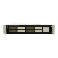
iPAM400 – Product Manual
U-0629-0171.doc – Issue: 04 complete, approved
Page 119 of 138
9 Product Specification
9.1 iPAM400
General
Supply Voltage (European standard) .................................. 230 V +/–10% RMS 50Hz AC / IEC320 inlet / T6.3A L 250 V fuse
Inrush Current (worst case)........................................................................................................................................ 24.2 A
Maximum AC Power Consumption........................ 745 VA (iPAM400 fully configured and all amplifier modules delivering
100 V 1 kHz sinewave into rated resistive loads)
DC Supply Voltage........................................................ 21 to 27.6 V (from nominal 24 V lead acid battery pack) / T25A fuse
(7W2 mixed signal D connector)
Quiescent DC Current (no amplifiers, @ 24 V supply) ............................................................................................... 450 mA
Maximum DC Current Consumption ............................................................. 6.25 A per 1 x MX100 100 W Amplifier Module
12.5 A per 1 x MX200 200 W Amplifier Module
25 A per 1 x MX400 400 W Amplifier Module
(21 V supply, modules delivering 100 V 1 kHz sinewave into rated resistive loads)
Internal Fuses.................................................................................................................................25 A TAC ATO 58 V fuses
Internal Lithium Battery .................................................................................................. DURACELL CR2032 or equivalent
Standard Configurations
1
............................................................................................... 1 x MX400 400 W Amplifier Module
2 x MX200 200 W Amplifier Module
4 x MX100 100 W Amplifier Module
1 x 200 W + 2 x 100 W Amplifier Modules
Loudspeaker Line Surveillance ................................................................... AC line surveillance
2
or DC line surveillance
3
Format .................................................................................................................... 2U 19-inch rack mounting metal frame
Colour .....................................................................................................................black front panel with silver annotation
External Interfaces
4
Audio Outputs .......................................................................up to 4 amplifiers each feeding up to four 100 V RMS outputs
(4-way pluggable cage clamp terminal block)
Microphone/Audio/Data Port
5
................................................................................................................................ 2 x ports
Audio Input ........................................................................................... balanced 0 dBu/10 kΩ/-20 dBu max. sensitivity
Auxiliary DC Supply Output ...........................................................................................................18-36 V (500 mA max)
depending on AC or DC supply, and battery conditions
Serial Interface ...............................................................................................................................................EIA RS485
19200 baud for microphone connection / 9600 baud for BMB01 connection
Connection .................................................................................................8-way pluggable cage clamp terminal block
Compatible with ASL paging microphones and BMB01 unit
6
1
The mainframe is fully populated in the standard configurations. However the mainframe does not need to be fully populated with
amplifiers, for example three MX100 amplifiers could be fitted, or a single MX200 amplifier.
2
AC line surveillance is BS EN5839 Part 8 compliant and requires one AEL01 or AEL02 Active End of Line Device used per
loudspeaker circuit. Loudspeakers do not require to be fitted with DC blocking capacitors.
3
DC line surveillance is BS EN5839 Part 8 compliant and requires all loudspeakers to be fitted with DC blocking capacitors, and uses
ASL EOL10K End of Line Resistors, with up to ten spurs per amplifier slot.
4
All located on the rear panel of the iPAM400.
5
Each port can support either an ASL microphone, or a BMB01 unit, or another audio source, or a BMB01 unit and another audio
source. Note that one port cannot support an ASL microphone and a BMB01 unit at the same time.
6
The iPAM400 can support up to nine BMB01 units.
ANS sensors can be configured on different BMB01 units. Up to twelve ANS sensors can be configured on each BMB01 unit. Any
number of ANS sensors configured on the iPAM400 can be assigned for each amplifier.

 Loading...