iPAM400 – Product Manual
U-0629-0171.doc – Issue: 04 complete, approved
Page 44 of 138
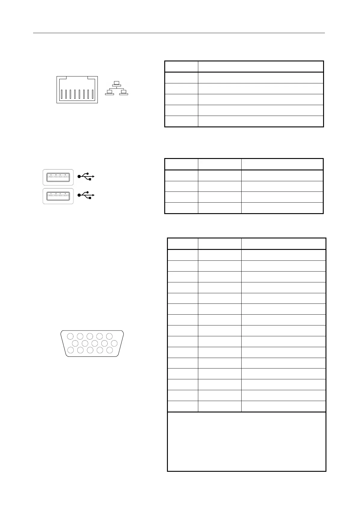
5.1.9 Ethernet Port
12345678
RJ45
ack
Pin No Description
1 Transmit+
2
Transmit−
3 Receive+
6
Receive−
4, 5, 7, 8 Unused
5.1.10 USB Ports 1 and 2
1 2 3 4
1 2 3 4
1
2
USB type A socket
Pin No Signal Description
1 VBUS + V Supply (output)
2
D−
Negative Data Channel
3 D+ Positive Data Channel
4 GND Ground
5.1.11 VGA Port
12345
678910
1112131415
15-way High Density D connector
(female)
Pin No Signal
1)
Description
1 RED Red Video
2 GREEN Green Video
3 BLUE Blue Video
5 GND Ground
6 RED_RTN Red Return
7 GREEN_RTN Green Return
8 BLUE_RTN Blue Return
9 +5 V +5 V DC
10 GND Ground (VSync, DDC)
12 SDA I²C data
13 HSync Horizontal Sync
14 VSync Vertical Sync
15 SCL I²C clock
4, 11 N/C Not connected
Shell Screen For cable screen
1) VESA DDC2 pinout.
2) DDC = Display Data Channel
I²C= Inter-Integrated Circuit
SCL = Serial Clock
SDA = Serial Data
VESA = Video Electronics Standards
Association
VGA = Video Graphics Array