iPAM400 – Product Manual
U-0629-0171.doc – Issue: 04 complete, approved
Page 47 of 138
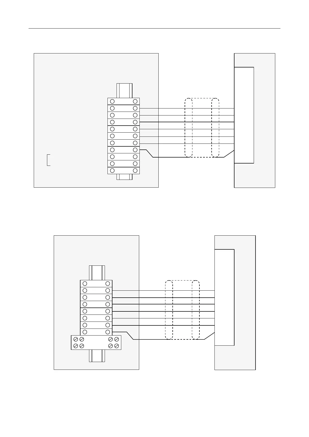
Figure 17 SAP02 Station Announcement Point connection
SAP02 ENCLOSURE
iPAM400
INPUT 1
or
INPUT 2
SCRN
IN+
IN-
0V
+V
DXP
DXN
SCRN
1 2 3 4 5
AUDIO+
AUDIO-
0V SUPPLY
+V SUPPLY
MIC DATA DXP
MIC DATA DXN
GROUND
6
GROUND
7 8
COMMISSIONING DATA DXP
COMMISSIONING DATA DXN
GROUND
NOT USED
(
See Note 1
)
Notes (Figure 17):
1) Refer to the user documentation specific to the SAP02 for details; see Table 7 (page 132).
2) Refer to Section “6.1 Generating a Configuration File” (page 59) for configuration details.
Figure 18 Single RRM02 Remote Radio Microphone connection
RRM02 ENCLOSURE
iPAM400
INPUT 1
or
INPUT 2
SCRN
IN+
IN-
0V
+V
DXP
DXN
SCRN
1 2 3 4 5 6 7
AUDIO+
AUDIO-
0
+
DXP
DXN
RELAY
SHIELD
(
See Note 1
)
Notes (Figure 18):
1) Refer to the user documentation specific to the RRM02 for details; see Table 7 (page 132).
2) Refer to Section “6.1 Generating a Configuration File” (page 59) for configuration details.