Chapter 4 INTERFACE SETTINGS
129
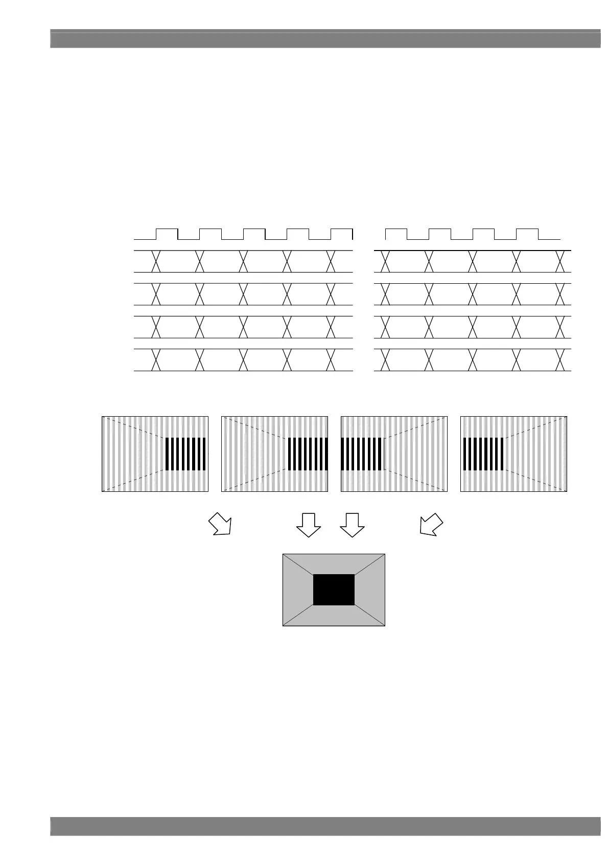
[5] MODE4 ×4 Mode (Quad Link) (Dividing Cross Mode)
Using channels 1 and 2, the right half of the image is output; similarly, using channels 3 and 4, the left half of the
image is output. The pixel assignment is given below.
Given here as an example of the resolution is 1920 × 1080, the dot clock frequency is 592 MHz with the 10 bits
output.
The ×4 mode is an output mode designed for the inspection of flat panel devices which support the Full HD 240 Hz
output. By connecting the output of the VG generator to the IA-1540 (iTMDS-LVDS converter box) and by halving the
output in the converter box,
The explanation concerns the signals of the four channels output from the VG generator. For an explanation
concerning an 8-channel output from LVDS, refer to section “4.13.3 Data transfer systems (V-By-One HS).”
CLK
148MHz
1CH
2CH
3CH
4CH
・・・
D 952 D 954 D 956 D 958
[9:0] [9:0] [9:0] [9:0]
D 0
[9:0]
D 2 D 4 D 6
・・・
[9:0] [9:0] [9:0]
D 953
[9:0]
D 955 D 957 D 959
[9:0] [9:0] [9:0]
[9:0]
・・・
[9:0] [9:0] [9:0]
D 1 D 3 D 5 D 7
D 1912 D 1914 D 1916 D 1918
[9:0] [9:0] [9:0] [9:0]
D 960
[9:0]
D 962 D 964 D 966
・・・
[9:0] [9:0] [9:0]
D 1913
[9:0]
D 1915 D 1917 D 1919
[9:0] [9:0] [9:0]
[9:0]
・・・
[9:0] [9:0] [9:0]
D 961 D 963 D 965 D 967
1CH 2CH 3CH 4CH



 To Next Page