Peripheral Devices
492 9836 3521 01
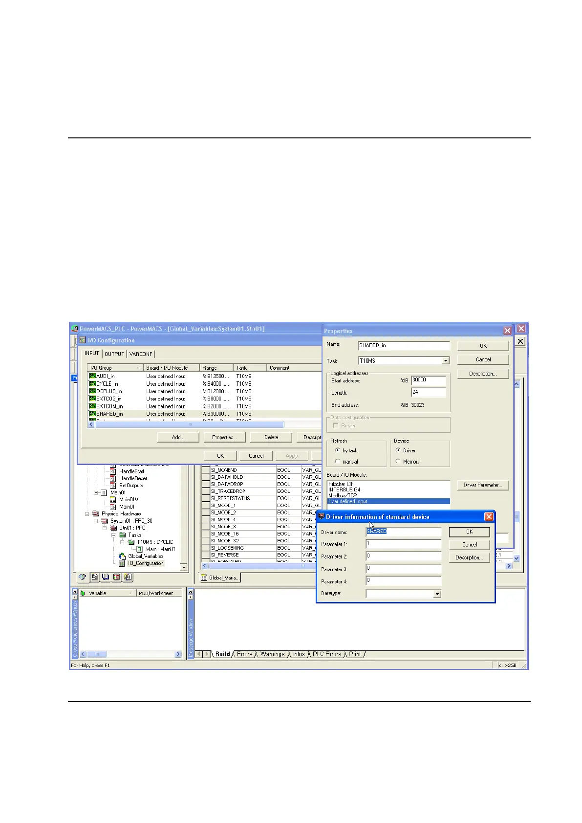
the SHARED driver to correctly map the total sizes of the respective input and output data areas defined
in the first step.
The addresses for inputs and outputs starts at 30000 and are logical only. Signals added here must also
have the prefixes “SI_” or “SO_” to be able to map to fieldbus and I/O devices.
Note! All numerical values are written and read as Big Endian values, commonly referred to as Motorola
format.
When the variables are declared you are free to refer them from any POU (Program Organization Unit)
you have, or will, declare in the PLC project.
After mapping the input and outputs variables the next step is to configure the SHARED driver to copy the
input and output data from the fieldbus to the PLC and vice versa. This is done using the I/O Configuration
dialogue which is invoked by double-clicking on the icon for IO_Configuration worksheet of station that has
the fieldbus interface mounted.
 Loading...