SmartROC D65 Tier 4 Final 14 Options
199
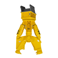
Measuring voltage/power
Connecting the I/O tester
1.
Connect the I/O tester between the I/O module input and the guard as illustrated.
2.
Measure the voltage according to the table.
Checking the digital outputs
There are two digital outputs designated A and B in each contact.
Pin Function
1 +24V DC
2 Signal B
3 GND
4 Signal A
5 GND
Table22: Pin configuration
Measuring voltage/power
1.
Connect the 5-position connector on the I/O tester between the output of interest on
the I/O module and the valve as illustrated.

 Loading...