SmartROC D65 Tier 4 Final 14 Options
200
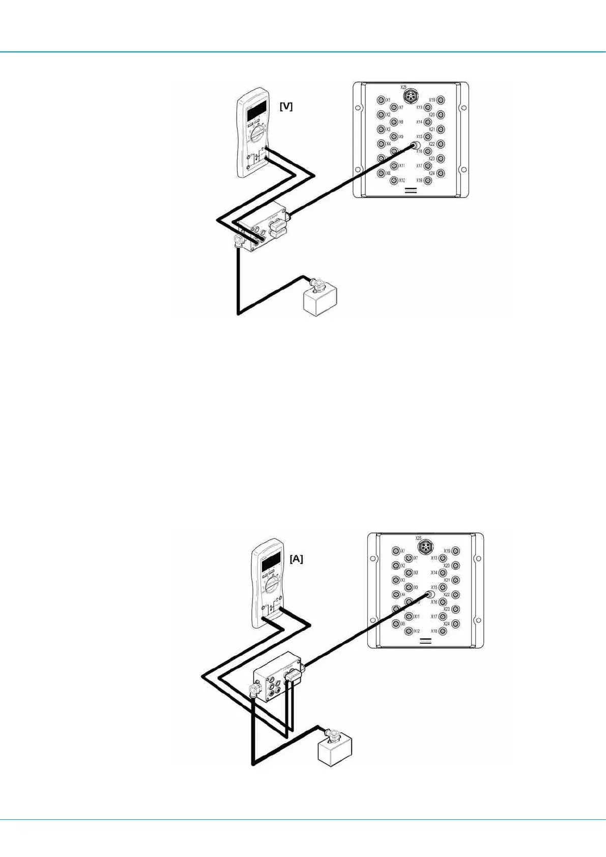
Connecting the I/O tester
2.
Connect the 5-position connector on the I/O tester to an unoccupied 5-position con-
nector in the I/O module.
3.
Connect the multimeter between GND and the +A or +B output that is of interest.
4.
Activate the function. Normally, the multimeter will read ~ 24V.
Fault indication
n If the valve is not activated, there is an open circuit in the cable running to the valve or
in the coil in the valve.
Measuring current
1.
Connect the 5-position connector on the I/O tester between the output of interest on
the I/O module and the valve as illustrated.
Connecting the I/O tester

 Loading...