723–0018 /02 F70108
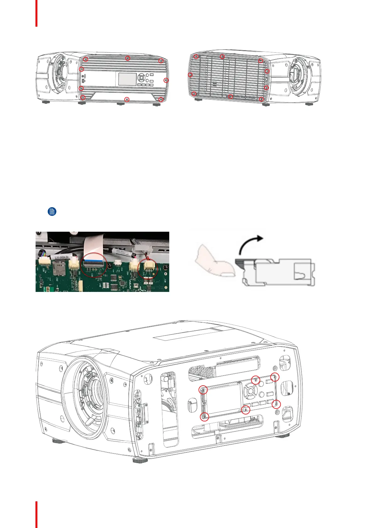
Image 17-7: Left sidecover Image 17-8: Right sidecover
17.4 Removing peripheral PCBs
17.4.1 Removal of display and keypad module
1. Remove the PCB Main cover, see chapter 19.1.1
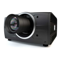
2. 1. Disconnect the Flex Cable from PCB main (J20) by gently lifting up the tab on the connector and remove
cable from the connector.
3. 2. Disconnect PwrKeybpoard cable from PCB main (J19).
Note: Be gentle handling flex cable and lock mechanism.
Image 17-9 Image 17-10
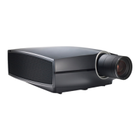
4. 3. Remove 6 screws TX10 M3x12, assembly can now be separated from left frame.
Image 17-11
Assembly hierarchy