723–0018 /02 F7032
534-0066-00 395 Temp Inlet Outlet
534-0070-00 395 Comm Cleanup Wheel 1 PCB Main J17 PCB CW Board J1
534-0071-00 395 Power Hub 1 PCB Hub J29 PCB Power J3
534-0029-00 NTC Laser Internal 12
PCB Hub J18 Sensor Opcal H and V
534-0035-02 390 Peler DuePoint PCB Hub J25 Peler DewPoint
PCB Hub J39 NTC DMD Front and Rear
534-0043-01 390 Power Keyboard 1 PCB Main J19 Keypad
534-0044-01 390 IR Top 1 PCB Main J7 IR Reciver J1
534-0028-00 390 Motor Opcal Filter
535-0002-00 395 Switch Boom 1 534-0001-04 Switch Boom
535-0003-00 395 Switch Iris
535-0005-00 Fan Blower 126x127x31 12V
535-0006-00 395 Switch Thermal DMD 1 PCB Main J12 Switch Thermal DMD
535-0007-00 395 Cable IR LED 1 PCB Hub J5 IR LED
534-0072-00 395 Power Laser 1
Comment: Connecons will be self explanatory, due to cable length vs
connector distance.
534-0031-01 390 Sensor Opcal H and V 2
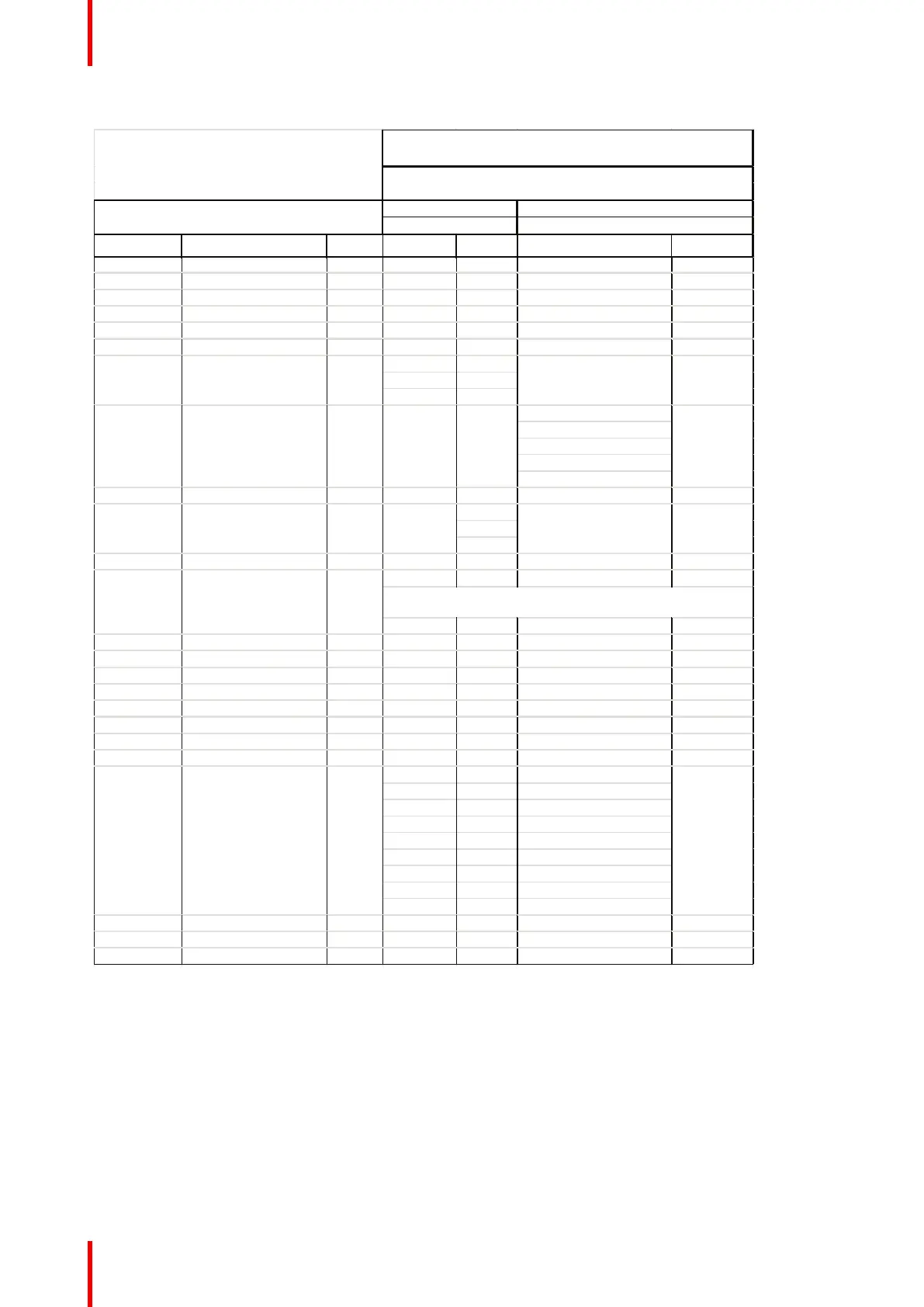
Partnumber Descripon Quanty PCB Name Conn. No. PCB Name Conn. No.
Note: Cables with no Connecon 2, indicates that they ends up in a
complete module assy.
Cable art. no.,specificaons, quanty
Image 5-4: Cabling Matrix, påart 2
5.5 Firmware
About
The functionality of the projector is based around a FPGA core that realizes all signal-processing, without the
need for separate special signal processing devices. Most of the functionality in the unit is therefore defined in
firmware.
To enable a maximum level of freedom to configure of the system, most functionality of the PCB Main is
programmed through FPGA housekeeping. Firmware flash is simply performed by saving the updated
GP7 system functional description