723–0018 /02 F70154
21.1 Iris Assembly
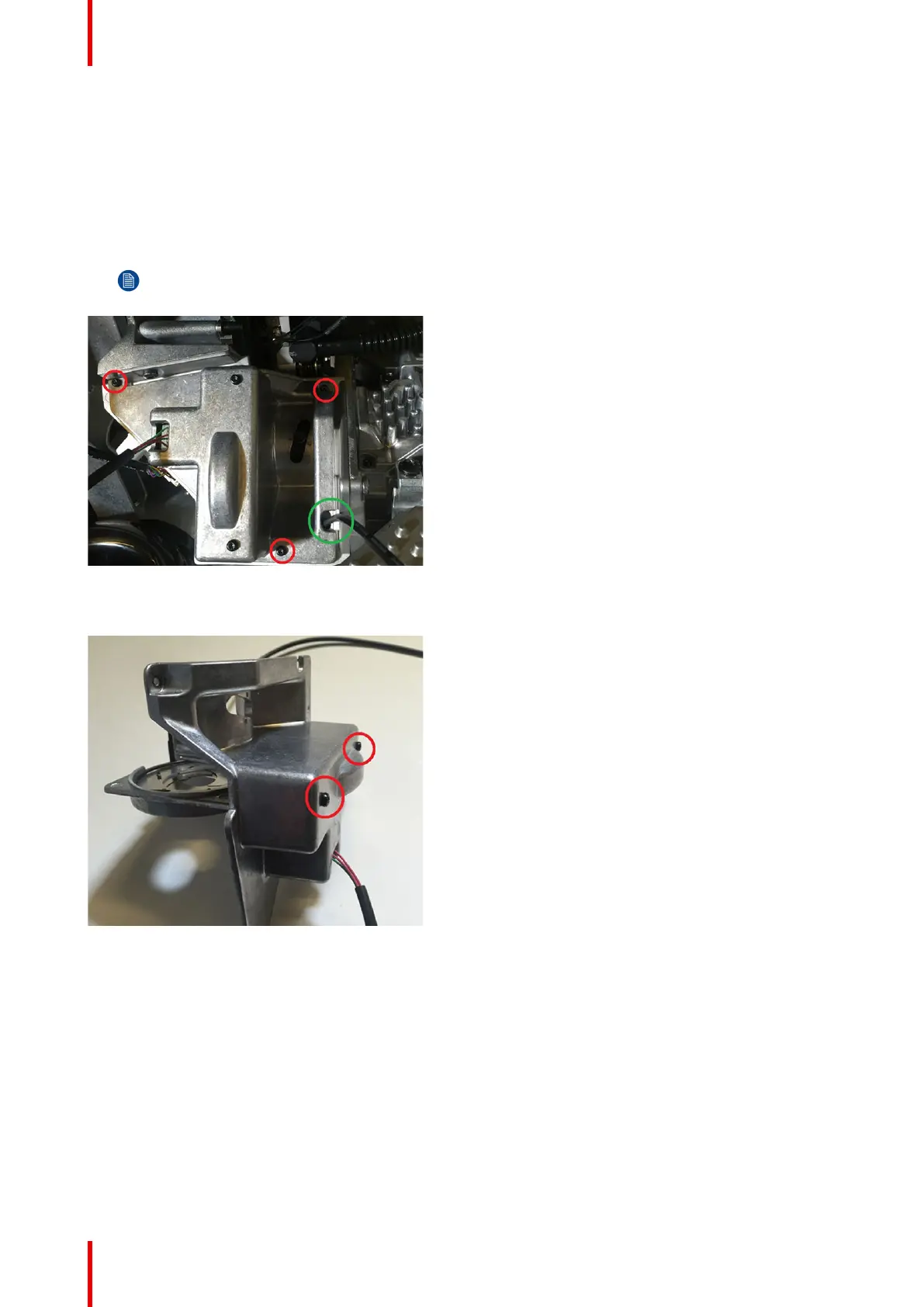
1. Remove 3 screws (TX8 M2.5x6) and carefully lift out Illumination Iris cover including IRIS assy.
2. Take note of cable routing of limit switch through groove in Illumination Iris cover, as illustrated (green) in
picture below.
Iris connects to PCB Thermal HUB conn: J4
Note:
This cable is not present on newer models of the F70 Projector.
Image 21-2
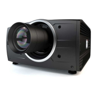
3. Remove 2 screws and release Iris assembly from the cover
Image 21-3
21.2 Relay tube assembly
1. 1. Remove two screws (TX8 M2.5x6), the clips and carefully lift out assembly.
In order to place the lens in correct position when assembling the Relay tube, use trace in the clip to match
grove in lens. The focus adjustment screw default position is center + 2mm towards.
Illumination Engine