723–0018 /02 F70 109
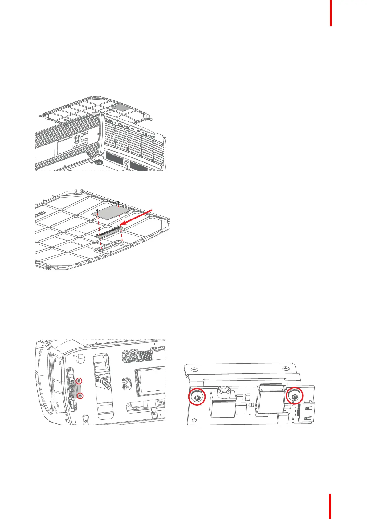
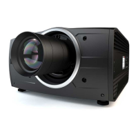
17.4.2 PCB GP6/GP7 IR Receiver and LED Board TOP
This PCB contains both the IR Receiver and the status indicator LED.
1. 1. Remove 2 screws (TX8 PT25x8) securing the PCB IR Receiver board to top cover. Lift up the PCB. The
LED lens can now also be removed. When reassembling, be sure to position the tabs in an upwards position,
as indicated by the red arrow.
Location of the
IR Receiver board
Image 17-12
Image 17-13
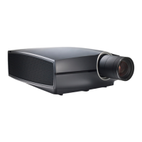
17.4.3 PCB Front USB & Trigger board
1. Release the two screws, TX10 M3x8 W/Lockwasher
2. Gently pull out the card, and release the cable from the PCB.
3. The PCB is secured to frame with 2 screws (TX10 M3x8 W/Lockwasher)
Image 17-14: Front USB and trigger board location Image 17-15: Bracket and PCB attachment
17.4.4 PCB IR Front
1. With front and top cover is removed, IR PCB can be pulled out of its holder. Disconnect the cable.
- IR Cable connects to PCB Lens Hub connector J17
Assembly hierarchy