723–0018 /02 F70146
20.1 General
WARNING: The TI loops modules are critical components, both with regards to laser safety and
proper handling of the components inside the module. Use rubber finger cots while handling optical
components to avoid staining or otherwise damaging optical coating. Imprints from the unprotected
fingers will cause overheating and damage of optical components.
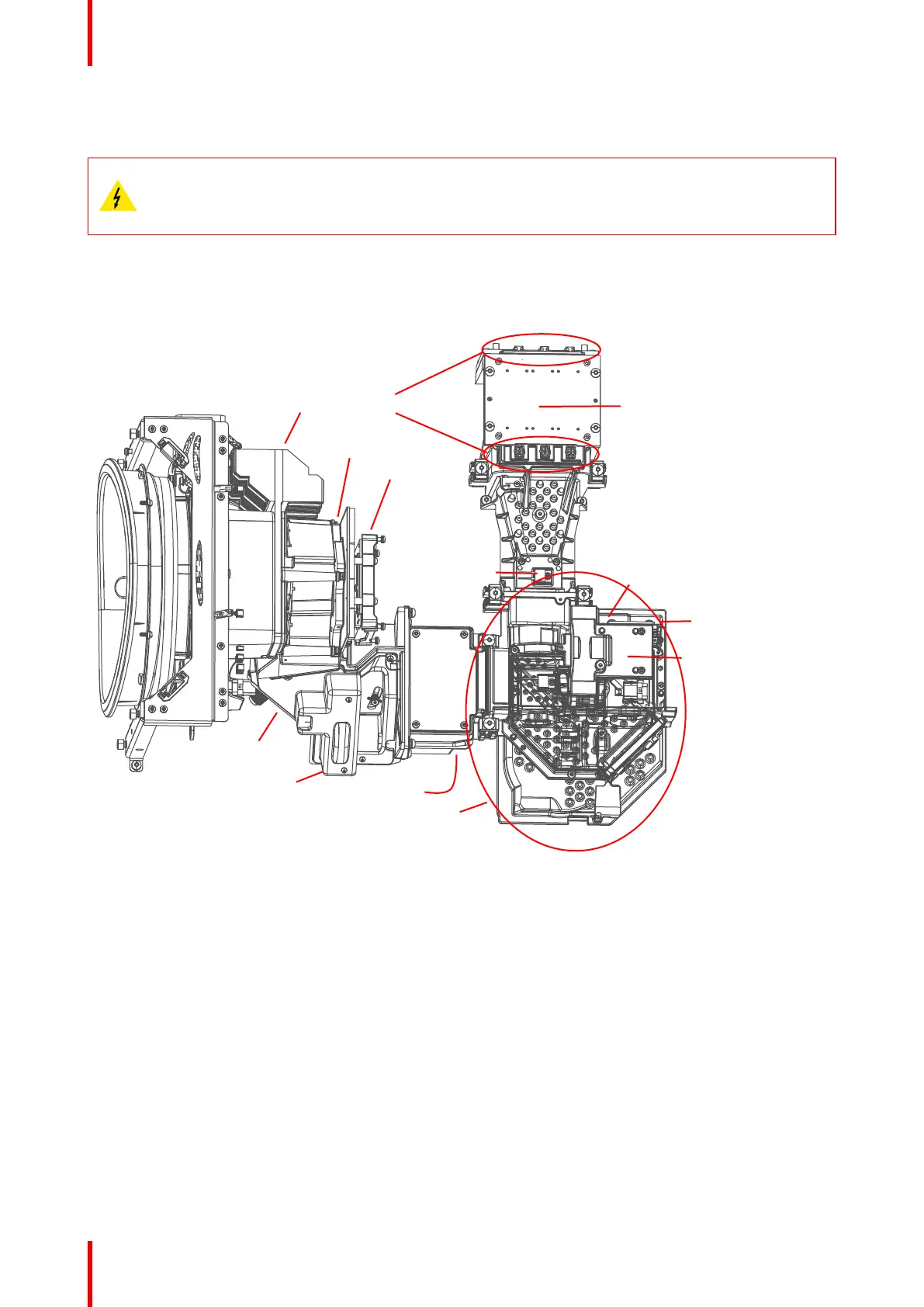
20.2 Overview Engine assembly
Laser Cluster
Laser cluster connectors
CLO
Color Wheel
Phosphor wheel
Thermal Switch
Peltier Front
IR LED
Fan Thermal Switch
Iris
TI Loop
DMD Assy
Pixel Shift Assy
Image 20-1
20.3 Opening and component identification.
20.3.1 Opening the Ti Loop
1. Remove the temperature sensors attached to this module.
2. 1. Remove 4 outer screws (Tx10 M3X6).Marked with red circles.
3. 2. Remove 3 screws (TX8 M2.5x6) marked with green circles, and then the PW Cover.
4. 3. Once the small cover is removed, the 4th TX10 M3X6 screw will be visible and you will be able to remove
Engine Blue Loop Top cover.
TI loop