723–0018 /02 F70 143
19.11 PCB Thermal Hub Board
19.11.1 PCB Thermal Hub board
To allow easier access during the following procedures, the PCB lens hub board including bracket
Hub board top and bottom can be removed.
1. Disconnect all cables.
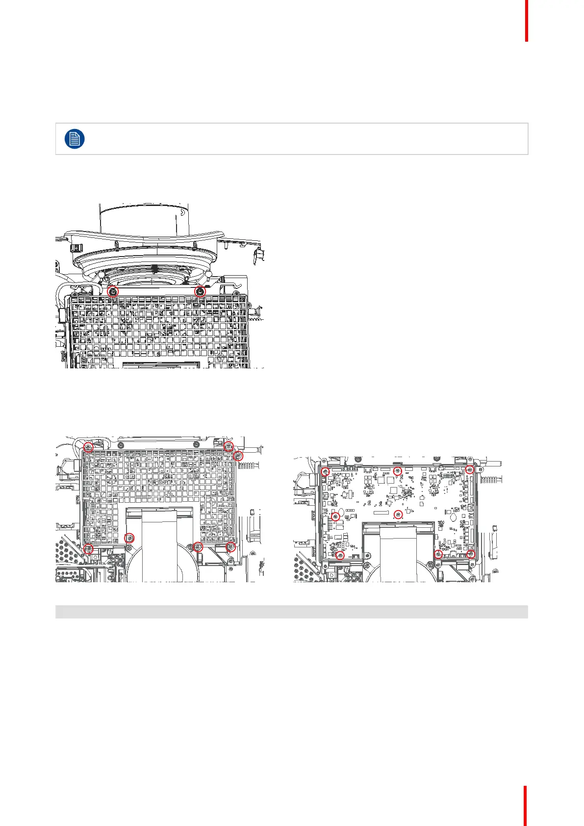
2. Release 2 screws (Tx10 M3x8) towards the lens.
Image 19-21
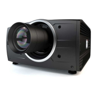
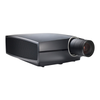
3. Release 7 screws (Tx10 M3x6) and remove Bracket Hub Top.
4. Remove 8 screws (Tx10 M3x10), disconnect all cables and remove the board.
Image 19-22 Image 19-23
Cable overview (from clockwise), as shown in figure below.
1. CLO (F90 4K only, Constant light output) i20. FanIR-R (FS90 only)
2. M_Iris 21. Pump 1-2-3-4
3. SW_Iris 22. Pump 5
4. M_Filtr 23. Mainboard 2 (HDMI)
5. Lensshift -H (Horizontal) 24. Peltier F
6. Lenspos-H (Hor.) 25. NTC-F
7. Lens 26. DPS
8. FPCA HK JTAG (Not in use). 27. FAN PCB
9. Fan 28. Mainboard1
10. Lensshift-V (Vertical) 29. Fan IR L (FS90 only)
Technical operations