723–0018 /02 F70110
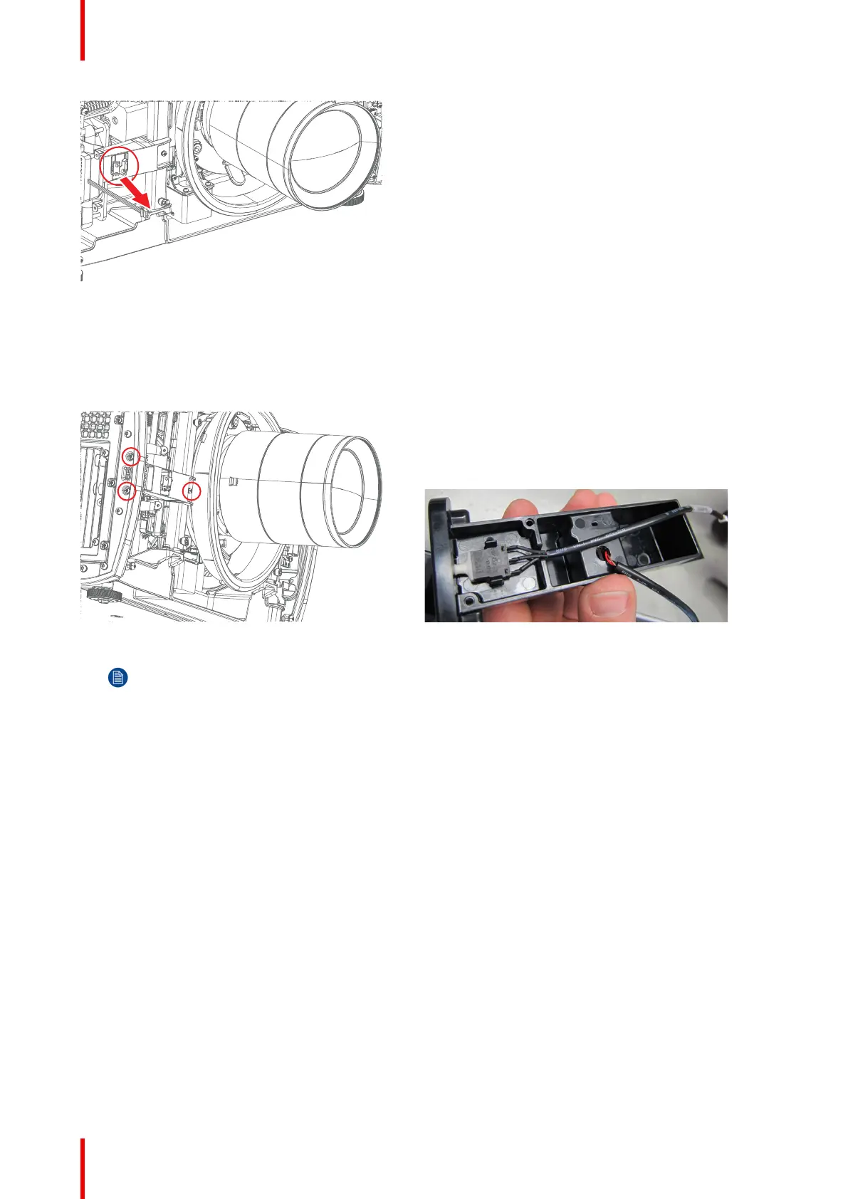
Image 17-16: Location of IR PCB
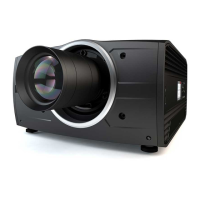
17.4.5 Switch Air/smoke filter
1. 1. Remove 3 screws TX10 M2x8 releasing IR Holder front from side-frame & bracket lens support.
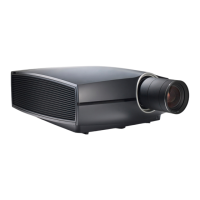
2. 2. Carefully open clips securing the switch and lift out.
Image 17-17 Image 17-18
Note: Ensure the switch is placed flat on bracket floor with the two side locks properly holding the
switch
- Switch connects to PCB Main J13.
17.4.6 PCB Temp sensor board #1 (Inlet)
Removing complete PCB Main Assy
The Temp sensors are located under the PCB Main board. It is possible to remove the complete Main board
assy in a simple way to get access to the sensors.
Remove 5 screws, release the cables attached to the PCB, and lift of the PCB Main assembly.
Assembly hierarchy