723–0018 /02 F70142
Image 19-19
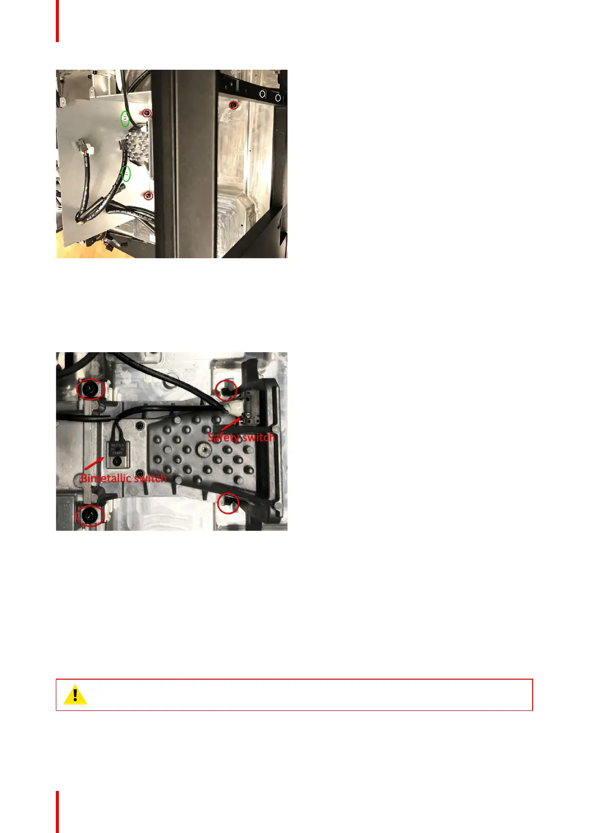
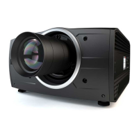
3. Remove Safety Switch and Bimetal switch.
4. Release two screws (TX20 M50X45) opening the Dow Tail clamps. This will release the laser interface form
the TI loop (not necessary to open fully).
5. Remove two screws securing the laser interface to the base plate (Tx20 M4x12)
Image 19-20
19.10 Install new laser interface
Position the new Laser Interface to the TI loop. The interface will “fall in” to a track, and will not be possible to
rotate vertically when it is in correct position. The line between the interface and the TI Loop will be narrow and
paralell.
Hold the interface in place with one hand, while entering the two M4x12 screws, and thereafter apply the
clamps and tighten them up. Ensure correct position and fit also for the clamps.
Tighten up the two M4x12 screws.
CAUTION: There shall be no bias between the laser interface and the TI Loop. This is a safety
issue. This will be obtained using the method described above.
Technical operations